


5-4 Wiring Diagrams TP-5695 12/93
Four-Lead Reconnectable (Single-Phase) Generator Sets Where Generator
Output Can Be Reconnected For 120 volt or 120/240 volt, 60 Hz,
110 volt or 110/220 volt, 50 Hz
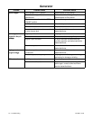
NOTE
When a generator set is reconnected to a voltage
different than nameplate voltage, notice should be
placed on the unit indicating this change. Decals for this
purpose are available from authorized Kohler
dealers/distributors.
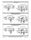
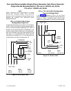
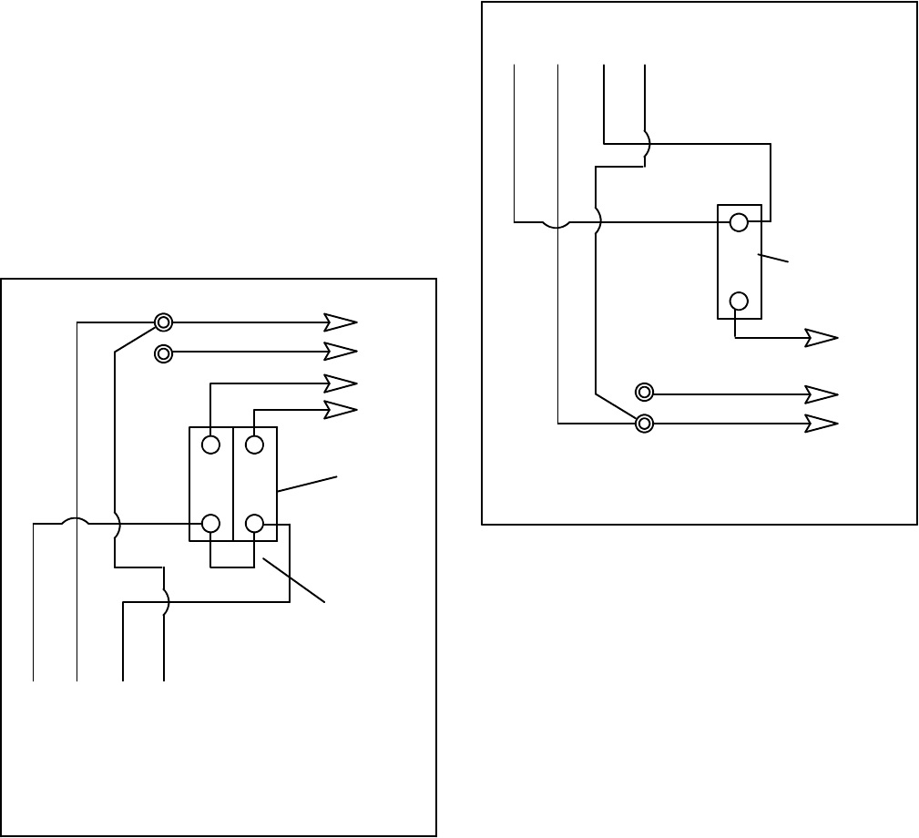
120- or 110-Volt 3-Wire 2-Pole
Configuration--Figure 5-4
Jumper lead to be placed on line side of circuit breaker.
Leads L1 and L2 can either be left as separate leads or
can be connected together depending upon which is
practical for the given application. Regardless of the
number of phase (black) leads used in the application,
both circuit breakers must have leads attached to the
load side. It is recommended that jumper lead be
maintained for all straight 120- or 110-volt systems since
it helps balance the load of the generator set.
4 3 2 1
Stator Leads
LO
GRD.
L2
L1
LO (Neutral)
Ground
Load Side
Line Side
Circuit
Breaker
Jumper
Lead
60 Hz 50 Hz
L0--L1 120 volt 110 volt
L0--L2 120 volt 110 volt
Figure 5-4. With Jumper Lead
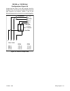
120- or 110- Volt 2-Wire Configuration
Figure 5-5 (Single Pole)
If the installation requires a 120 or 110 volt, 2-wire
system, a single-pole circuit breaker must be used. See
Figure 5-5. When connecting stator phase leads
together, the output lead (L1) must be sized accordingly.
4 3 2 1
Stator Leads
LO
GRD.
LO (Neutral)
Ground
Load
Side
Line
Side
1-Pole
Circuit
Breaker
L1
60 Hz 50 Hz
L0--L1 100-120 volt 100-120 volt
Figure 5-5. 120 Volt, 2-Wire