TP-5695 12/93 Installation 6-7
Cooling Systems
General
The following features are necessary in the cooling
system.
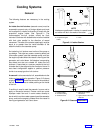
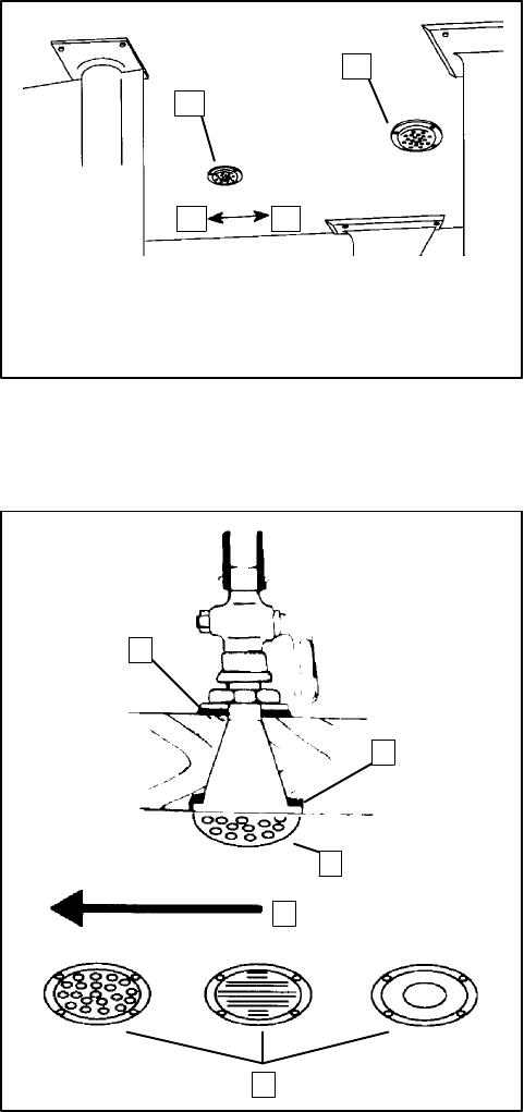
An intake thru-hull strainer (seacock cover) must be
screened to prevent entry of foreign objects and must
not be aligned (in relation to direction of travel) with the
propulsion engine intake. See Figure 6-11. The
recommended thru-hull strainer should be flush
mounted. Strainers with slotted holes must be installed
with their slots parallel to the direction of vessel
movement. The area of the strainer opening(s) must be
equal to or greater than the inside diameter of the
waterline hose to the seawater pump.
An intake thru-hull strainer must not be of the scoop or
cup design. This style can cause a ramming effect and
force water upward, past the seawater pump, and into
the engine cylinders when the vessel is moving and the
generator set is shut down. Hull designs incorporating
sea chests are also not suitable for intake thru-hull
strainers. A sea chest is a concave molded-in-the-hull
chamber that is also aligned to the direction of travel. A
sea chest configuration applies a positive pressure
similar to a scoop-type thru-hull strainer.
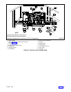
A seacock is to be mounted to hull, assembled onto the
intake and accessible for operation. Figure 6-12 shows
a typical installation. Install the canvas on the outside of
the hull, and the canvas or rubber packing on the inside
of the hull.
If caulking is used to seal the seacock, be sure not to
apply an excessive amount. Excess caulk can cause
improper water flow and in some cases develop a
barrier which can force water upward, past the seawater
pump, and into the engine cylinders when the vessel is
moving and generator set is shut down.
NOTE
Intakes are positioned in relation to vessel travel
so neither will be in the wake of the other.
1
2
4 3
1-789
1. Generator Set Intake
2. Propulsion Engine
Intake
3. Aft
4. Fore
Figure 6-11. Intake Strainer
1
2
3
4
1. Inside Packing
2. Outside Packing
3. Seacock Cover
4. Direction of Vessel
Movement
5. Typical Intake Thru-Hull
Strainers
5
1-789
Figure 6-12. Seacock Installation


