


TP-5695 12/93 Installation 6-9
TOTAL HOURS
00 000
1/10
10A
FUSE
BATT.
CHRG.
INPUT
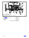
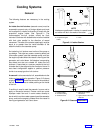
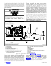
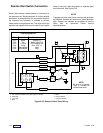
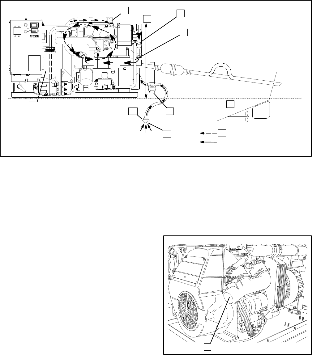
NOTE
Use two hose clamps on each
end of all flexible exhaust
hose connections.
1. Exhaust Manifold
2. 3 ft. (1 m) Max.
3. Engine-Driven Seawater Pump
4. Heat Exchanger
5. Waterline
6. Seawater Strainer
7. Intake Strainer
8. Engine Coolant
9. Seawater
10. Seacock
11. Coolant Recovery Tank
1
2
3
4
5
6
7
8
9
10
11
STOP/START
258000-D
Figure 6-15. Closed/Heat Exchanger Cooling System
Exhaust Systems
General
Water-cooled exhaust lines should be used in all marine
installations. The hose used for the lines should have a
2 in. (51 mm) inside diameter. Keep the lines as short
and straight as possible. The use of two hose clamps on
each end of flexible exhaust hose connections is highly
recommended. ABYC Safety Standards P-1.6.c
recommend a pitch of at least 1/2 in. (12.8 mm) per
running foot (30.5 cm). Use flexible steam hose
conforming to UL Standard 1129 for “Engine wet
exhaust components” between the mixing elbow and
the exhaust outlet. A silencer should be independently
mounted to eliminate any stress on the exhaust system
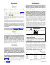
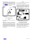
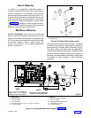
and exhaust manifold/mixer elbow. See Figure 6-16 for
the exhaust connection to the mixer elbow.
1
1-894
1. Seawater/Exhaust Outlet
Figure 6-16. Mixer Elbow/Exhaust Connection