Rosemount Model 444 Alphaline Temperature Transmitters
6-4
LCD Meter
Assembly
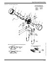
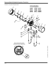
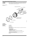
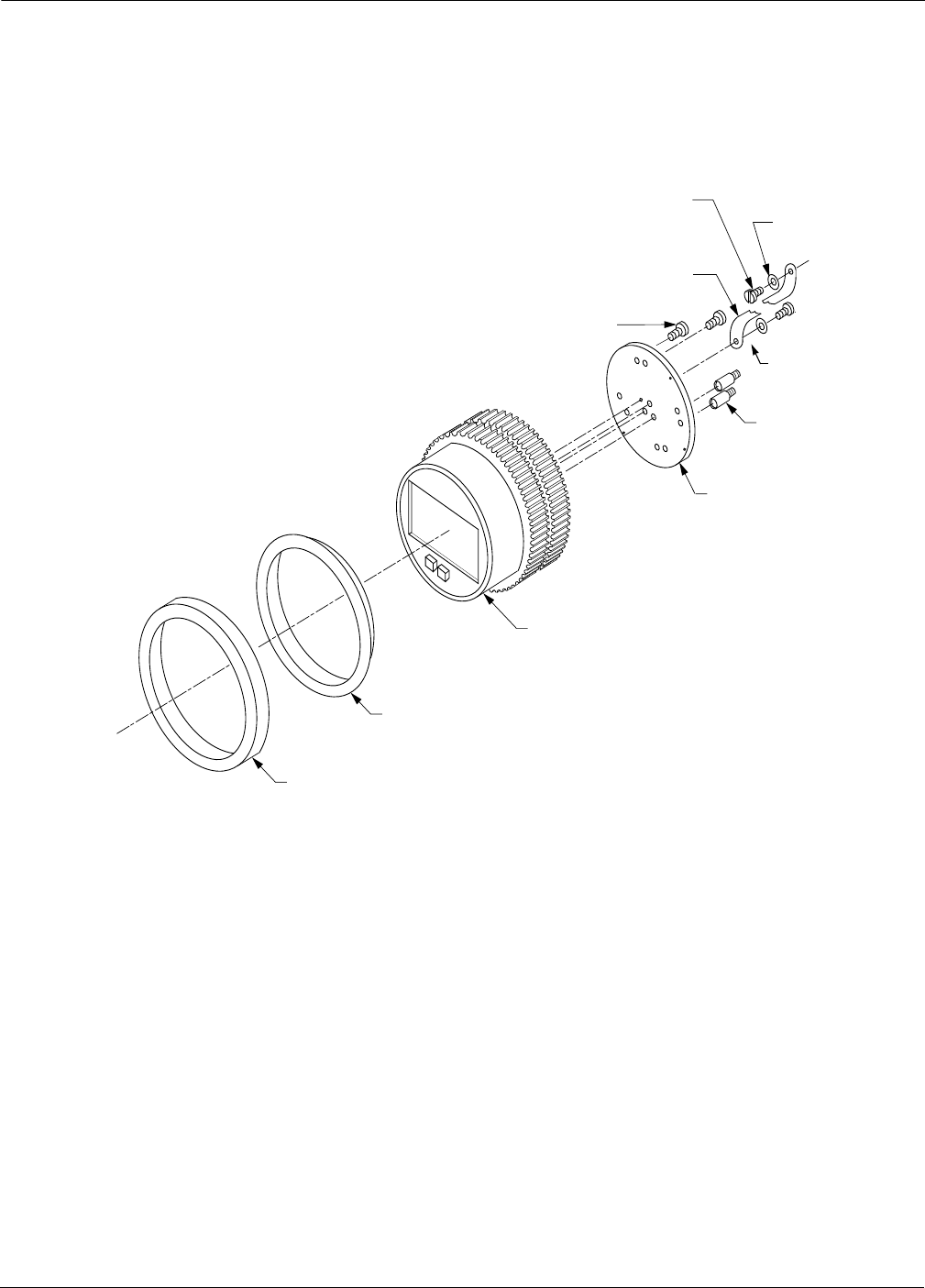
Figure 6-3 shows the mounting hardware required to properly install the LCD
meter on a Model 444 transmitter. This mounting hardware may also be used
with the Rosemount universal (analog) meter.
FIGURE 6-3. LCD Meter
Exploded View
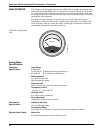
LCD Meter
Specifications
Functional
Specifications
Input Signal
4–20 mA dc.
Meter Indication
4-digit LCD showing –999 to 9999. A 20-segment bar graph directly represents
the 4–20 mA current.
Scaling/Calibration
4 mA Point Limits: –999 to 1000.
Span limits: 0200 to 9999.
The sum of the 4 mA point and span must not exceed 9999.
Adjustments are made using non-interactive zero and span buttons.
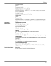
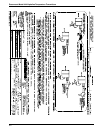
Hazardous Locations Certifications
Approved for use with Rosemount Models 444, 751, 1135, 1144,
and 1151.
CoverFoamSpacer
Cover Bushing
Mounting Plate
Meter (Meter may be rotated
in 90 degree increments)
Terminal Screws (Mount
into Transmitter “Test”
Terminal Block)
Mounting Screws
Retaining Straps
Mounting Screw into Housing
Strap Washer
Mounting Screw into
Mounting Plate
751-0264B


