


Rosemount Model 444 Alphaline Temperature Transmitters
2-12
Preliminary Checkout
1. For any Model 444 unit, first verify that the transmitter is calibrated to
the required range. Calibration is usually performed by substituting an
input in place of the sensor, and this is most conveniently accomplished
prior to sensor connection. Refer to the calibration procedures in Section
4 Maintenance and Troubleshooting.
Input Connections
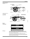
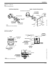
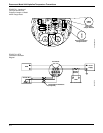
2. Model 444RL: Connect the RTD leads as shown in Figure 2-6a, b, c, d, or
e depending upon the lead compensation method used.
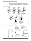
Model 444T series: Connect the thermocouple leads as shown in Figure
2-6f. Polarity is important; be sure to identify the leads accurately. The
negative lead is usually red; if there is no color coding, the characteristics
provided in Figure 2-7 may be helpful.
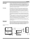
Model 444MV: If using the transmitter as a millivolt-to-milliampere
converter, use ordinary copper leads for input connections as shown in
Figure 2-6f. If using the transmitter with two thermocouples to measure
differential millivolt, connect the thermocouples as shown in Figure 2-6g.
The “high” thermocouple causes the transmitter output to increase when
its temperature increases relative to the “low” thermocouple. Grounded
thermocouples cannot be used for differential measurements.
Models 444LL and LM: In these low-power option packages, the RTD
leads are connected the same as in the conventional RTD arrangements
shown in Figure 2-6a, b, c, and d.
Output Connections
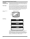
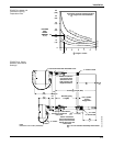
3. For all 4–20 mA models, use ordinary copper wire of sufficient size to
assure that the voltage across the transmitter power terminals does not go
below 12 V dc (See Figure 2-3). For multi-channel or intrinsically safe
installations, see applicable paragraphs in this section.
Model 444RL: Connect current signal leads as shown in Figure 2-6a, b, c,
or d.
Model 444T series: Connect current signal leads as shown in Figure 2-6f.
Model 444MV: Connect current signal leads as shown in Figure 2-6f or g.
Models 444LL and LM: Connect current signal leads as shown in Figure
2-6e.
Final Checkout
4. For all models, recheck the polarity and correctness of connections; then
turn the power on.