


6-3
Options
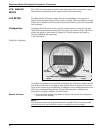
Position the Decimal
Point and Select the
Meter Function
2. Press the left and right configuration buttons simultaneously and release
them immediately.
3. To move the decimal point to the desired location, press the left
configuration button. Note that the decimal point wraps around.
4. To scroll through the mode options, press the right configuration button
repeatedly until the desired mode is displayed. See Table 6-1.
Store the Information 5. Press both configuration buttons simultaneously for two seconds. Note
that the meter displays “----” for approximately 7.5 seconds while the
information is being stored.
Set the Display
Equivalent
toa4mASignal
6. Press the left button for two seconds.
7. To decrement the display numbers, press the left configuration button and
to increment the numbers, press the right configuration button. Set the
numbers between –999 and 1000.
8. To store the information, press both configuration buttons simultaneously
for two seconds.
Set the Display
Equivalent
to a 20 mA Signal
9. Press the right button for two seconds.
10. To decrement the display numbers, press the left configuration button on
the display and to increment the numbers, press the right configuration
button. Set the numbers between –999 and 9999. The sum of the 4 mA
point and the span must not exceed 9999.
11. To store the information, press both configuration buttons simultaneously
for two seconds. The LCD meter is now configured.
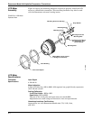
Replace the Cover 12. Make sure the rubber gasket is seated properly, replace the transparent
cover, and replace the retaining ring.
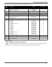
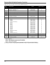
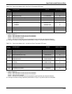
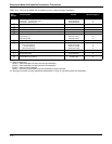
TABLE 6-1. LCD Meter Modes.
Options Relationship between Input Signal and Digital Display
Lin
LinF
Srt
SrtF
Linear
Linear with five-second filter
Square root
Square root with five-second filter
Square root function only relates to the digital display.
The bar graph output remains linear with the current signal.
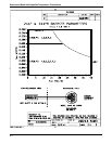
Square root response
The digital display will be proportional to the square root of the input current where 4 mA=0
and 20 mA=1.0, scaled per the calibration procedure. The transition point from linear to
square root is at 25% of full scale flow.
Filter response operates upon “present input” and “input received in the previous five second
interval” in the following manner:
Display = (0.75 ϫ previous input) + (0.25 ϫ present input)
This relationship is maintained provided that the previous reading minus the present reading is
less than 25% of full scale.