


Rosemount Model 444 Alphaline Temperature Transmitters
2-2
produce low-level signals proportional to their sensed temperature. Model 444
temperature transmitters convert the low-level sensor signal to a standard 4–20
mA dc signal that is relatively insensitive to lead length and electrical noise.
This current signal is then transmitted to the control room via two wires.
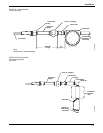
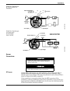
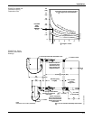
Figures 2-1, and 2-2 show recommended mounting configurations for
transmitter and sensor assemblies. See Section 6 Options for information
regarding Model 444 transmitter accessories.
MECHANICAL
CONSIDERATIONS
You can attach the transmitter directly to the sensor assembly as shown in
Figures 2-1 and 2-2. An optional mounting bracket permits the transmitter to be
mounted remotely from the sensor(s), either on a flat surface or attached to a
two-inch pipe (See Figure 2-11 on page 2-13). The choice of mounting method
must take into account a number of factors:
Mounting Stability
Mounting stability is an important consideration. The transmitter, though
rugged, may require supplementary support under high-vibration conditions,
particularly if extensive thermowell lagging or long extension fittings are used.
In such instances, the pipestand mounting technique shown in Figure 2-11 on
page 2-13 is preferable.
Access
Requirements
When choosing an installation location and position, take into account the need
for access to the transmitter.
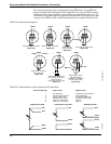
Housing Rotation You may rotate the transmitter in 90-degree increments to improve field access
to both compartments.
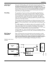
Terminal Side of
Electronics Housing
Make wiring connections through the conduit openings on the terminal side of
the electronics housing. Mount the transmitter so the terminal side is accessible,
and be sure to provide adequate clearance for cover removal.
Circuit Side of
Electronics Housing
The transmitter electronics are installed in the circuit side of the transmitter
housing. In case of electronic malfunction, provide adequate clearance for
circuit-side cover removal. Also, be sure to account for additional clearance if a
meter is to be installed. For more information regarding the meter option, refer
to Section 6 Options.