


2-5
Installation
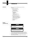
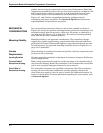
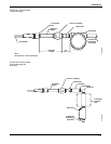
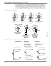
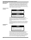
FIGURE 2-4. Field Wiring for
the Standard Model 444
Transmitters.
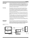
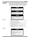
FIGURE 2-5. Field Wiring for
Low-Power Model
444 Transmitters
(444LL and LM).
Sensor
Connections
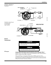
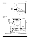
RTD Inputs
Various RTD configurations are used in industry; each configuration offers a
specific solution for compensating the effects of lead wire resistance. They
include 3- and 4-wire designs. The correct installation for each of these RTDs is
shown in Figures 2-6a and b on page 2-6.
If the transmitter is mounted remotely from the RTD, operation will be
satisfactory, without recalibration, for lead wire resistances of up to 2 ohms per
lead (equivalent to 200 feet of 20 AWG wire). In this case, the leads between the
RTD and transmitter should be shielded.
Optional
Ground
Span Adjust
Zero Adjust
RTD Input
(typical)
Meter Connections
and Signal
Test Points
{
{
(+)
(+)
(–) (–)
dc Power
–+–+
++––
+
444-0000C02A
(+) dc Power
(–) Common
Span Adjust
Zero Adjust
RTD Input
Shield
Power
Supply
AtoD
Converter
Optional
Ground
Output Voltage (+)
Output Load Limitation
Minimum Load = 100K
444-0000A02A
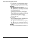
Explosion may result in death or serious injury. Do not
remove the instrument cover in explosive atmospheres
when the circuit is alive.
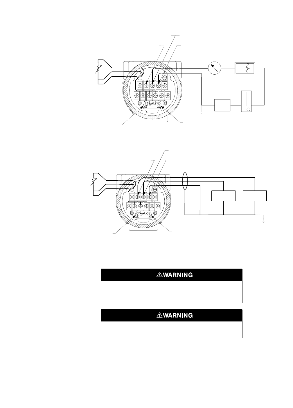
High voltage that may be present on leads can cause electrical
shock. Avoid contact with the leads and the terminals.