


Rosemount Model 444 Alphaline Temperature Transmitters
2-6
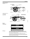
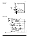
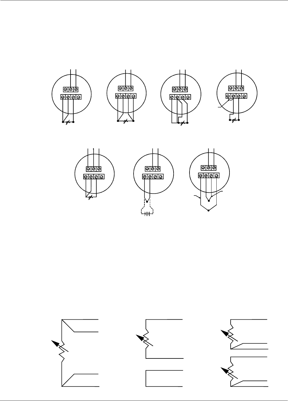
The correct connections for a compensation loop RTD and a 2-wire RTD are
shown in Figure 2-6c and Figure 2-6d, respectively. In a 2-wire RTD, however,
both leads are in series with the sensor element, so significant errors (0.1 °C)
could occur if the lead lengths are greater than one foot. For longer runs when
using a 2-wire RTD, attach a third lead and connect as shown in Figure 2-6a.
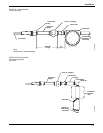
FIGURE 2-6. Sensor Wiring Diagrams.
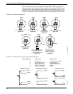
FIGURE 2-7. Characteristics of Thermocouple and RTD Input Wires.
–+
Signal
Model 444 with 3-Wire RTD
Figure 2-6a
Model 444 with 4-Wire RTD
Figure 2-6b
Model 444 with 2-Wire RTD
Figure 2-6d
Model 444 with
Comp. Loop RTD
Figure 2-6c
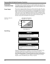
Model 444LL or 444LM
with 3-Wire RTD
Figure 2-6e
Model 444MV with Millivolt
Input or Model 444T Series
with Grounded or
Ungrounded Thermocouple
Figure 2-6f
Model 444MV used as
Differential Millivolt
Transmitter (T/C Junctions
must be ungrounded)
Figure 2-6g
–+
Signal
–+
Signal
–+
Signal
Jumper
+ Output Common –
Signal
–+
Signal
–+
Signal
White
Red
Red
White
Red
Red
White
White
Red
Black
Black
White
Red
High T/C
Low T/C
++ ––
–+
–+
White
Red
Red
444-0203A;B;C;D
Single Element RTD Compensation Loop RTD Dual Element RTD
Red
Red
White
White
Red
Black
White
Black
Red
White
White
Black
Green
Green
Thermocouple Type Positive Lead Negative Lead
J Iron (Magnetic) Constantan (Non-magnetic)
K Chromel (Non-magnetic) Alumel (Magnetic)
T Copper (Yellow color) Constantan (Silver color)
E Chromel (Shiny metal) Constantan (Dull metal)
R Platinum 13% Rhodium Platinum
S Platinum 10% Rhodium Platinum
444-0207A