Rosemount Model 444 Alphaline Temperature Transmitters
6-2
LCD / ANALOG
METER
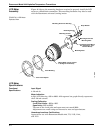
The LCD and analog meters provide local indication of the transmitter output.
Both meters attach easily to the terminal side of the transmitter.
LCD METER
The Rosemount
®
LCD meter plugs directly into the Model 444 to provide a
highly accurate digital display of the process variable. The meter adds no voltage
drop in the 4–20 mA current loop when connected directly across the transmitter
test terminals.
Configuration
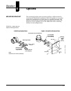
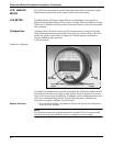
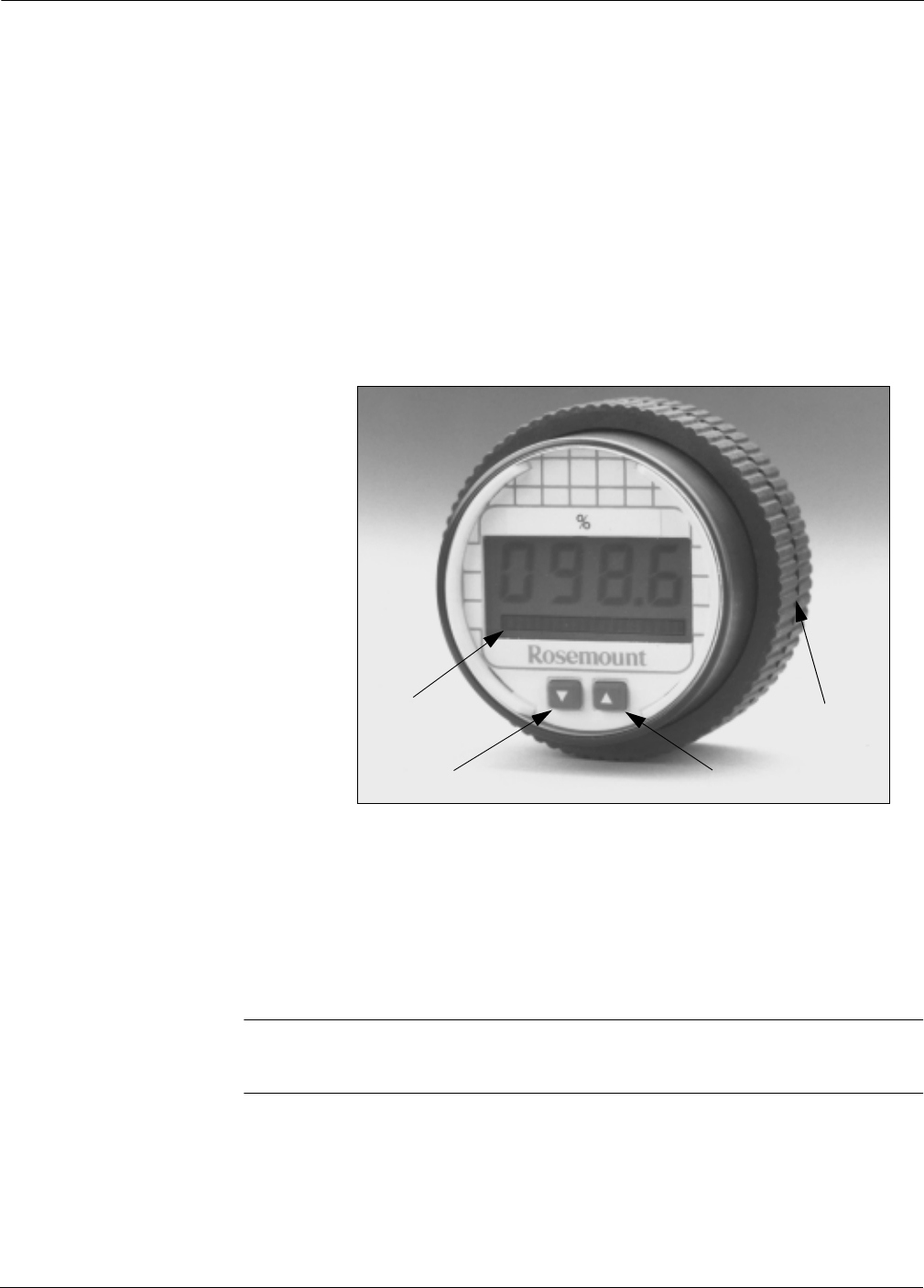
Configure the LCD meter to meet specific requirements by using the left and
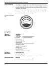
right calibration buttons located on the meter face as shown in Figure 6-2. The
analog bar graph is also shown in Figure 6-2. The 20-segment bar graph is
factory calibrated and represents
4–20 mA directly.
FIGURE 6-2. LCD Meter.
.
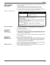
No calibration equipment is required to configure the LCD meter, but between 4
and 20 mA must exist in the loop in order for the meter to operate. The actual
value of the current is not significant. In addition, meter configuration does not
affect the transmitter/loop current. Use the following meter configuration
procedure to properly configure the LCD meter.
Remove the Cover 1. Unscrew the retaining ring shown in Figure 6-2 and lift the transparent
cover off of the housing.
NOTE
The LCD meter time-out is approximately 16 seconds. If keys are not pressed
within this period, the indicator reverts to reading the current signal.
Retaining
Ring
Right Configuration
Button
LeftConfiguration
Button
Analog
Bar Graph
LCD-001AB


