


5-9
Specifications and Reference Data
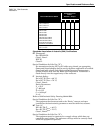
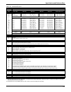
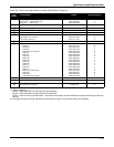
TABLE 5-3. 444 Model Structure.
Model Product Description
444 Alphaline Temperature Transmitter
Code Input Type
(1)
(1) Refer to Temperature Sensors, Assemblies , and Accessories Product Data Sheet, Rosemount pub. no. 00813-0100-2654 for information
about Rosemount sensor assemblies.
Temperature Span
Minimum Maximum
Base Temperature
Minimum Maximum
Upper Range Limit
RL1
RL2
RL3
Platinum RTD
100 ⍀ R
0
linearized output
45 °F (25 °C) 135 °F (75 °C)
125 °F (70 °C) 380 °F (210 °C)
360 °F (200 °C) 1080 °F (600 °C)
–58 °F (–50 °C) 300 °F (150 °C)
–58 °F (–50 °C) 300 °F (150 °C)
–58 °F (–50 °C) 300 °F (150 °C)
435 °F (225 °C)
680 °F (360 °C)
1380 °F (750 °C)
RL9 Special Input, Range or Accuracy (minimum span 3 ⍀)
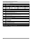
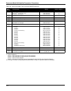
TJ1
TJ2
TK1
TK2
TK3
TE1
TE2
TT1
TR1
TS1
Thermocouple
Ty p e J
Ty p e J
Ty p e K
Ty p e K
Ty p e K
Ty p e E
Ty p e E
Ty p e T
Ty p e R
Ty p e S
180°F (100 °C) 540 °F (300 °C)
504 °F (280 °C) 1458 °F (810 °C)
180 °F (100 °C) 540 °F (300 °C)
504 °F (280 °C) 1510 °F (840 °C)
845 °F (470 °C) 2540 °F (1410 °C)
180 °F (100 °C) 540 °F (300 °C)
504 °F (280 °C) 1510 °F (840 °C)
180 °F (100 °C) 540 °F (300 °C)
1467 °F (815 °C) 3000 °F (1670 °C)
1467 °F (815 °C) 3000 °F (1670 °C)
–58 °F (–50 °C) 300 °F (150 °C)
–58 °F (–50 °C) 930 °F (500 °C)
–58 °F (–50 °C) 300 °F (150 °C)
–58 °F (–50 °C) 930 °F (500 °C)
–58 °F (–50 °C) 930 °F (500 °C)
–58 °F (–50 °C) 300 °F (150 °C)
–58 °F (–50 °C) 930 °F (500 °C)
–58 °F (–50 °C) 300 °F (150 °C)
0 °F (–18 °C) 1500 °F (815 °C)
0 °F (–18 °C) 1500 °F (815 °C)
840 °F (450 °C)
1400 °F (760 °C)
840 °F (450 °C)
2440 °F (1340 °C)
2500 °F (1370 °C)
840 °F (450 °C)
1830 °F (1000 °C)
750 °F (400 °C)
3200 °F (1760 °C)
3200 °F (1760 °C)
T_9 Special Range or Accuracy (minimum span 3 mV, maximum span 100 mV)
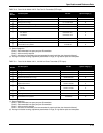
MV1
MV2
Millivolt
Millivolt
5mV 15mV
15 mV 45 mV
–2mV 8 mV
–2mV 20mV
23 mV
65 mV
MV9 Special Range or Accuracy (minimum span 3 mV, maximum span 100 mV)
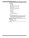
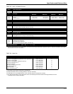
Code Loss of Input Indication
U
D
N
Upscale (standard for all input types)
Downscale
None (not available for platinum RTD inputs)
Code Calibration
1
2
3
Trim to IEC 751 Class B (RTD) or NIST Curve (thermocouple)
Trim to Specific Model 68/78/88 Calibration Schedule
Trim to Other Nominal Curve (customer must specify separately) (Note: Millivolt input must use Code 3.)
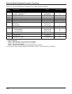
Code Meter Options
A
B
C
D
E
None
Integral Analog Meter, Special Scale (same as calibrated range)
Integral Analog Meter, 0–100% Scale
Integral LCD Meter, 0–100% Scale
(2)
Integral LCD Meter, Special Scale (specify range, mode, and engineering units)
(1)
(2) LCD Meters are only available with RL1, RL2, or RL3. (may be reconfigured in the field.)
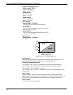
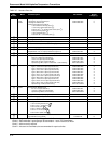
Code Mounting Bracket
1
2
None
Mounting Bracket for 2-inch Pipe or Surface Mounting
Code Hazardous Area Certifications
NA
E5
I5
E6
I6
E7
I7
N7
E8
I8
N1
No Certification Required
FM Explosion-Proof Approval
FM Intrinsic Safety and Non-incendive Approval
CSA Explosion-Proof Approval
CSA Intrinsic Safety Approval (444RL and 444T only)
SAA Explosion-Proof Certification
SAA Intrinsic Safety Certification
SAA Non-incendive Certification
CESI Explosion-Proof Certification (When ordering a transmitter with this option, place a W before the model number: W444.)
CESI Intrinsic Safety Certification (When ordering a transmitter with this option, place a W before the model number: W444.)
BASEEFA Non-incendive Certification (When ordering a transmitter with this option, place a T before the model number: T444.)
Code Options
Q4
A1
A2
2-Point Calibration Certificate
One (1) ½ NPT to M20 (CM 20) SST Thread Adapter
One (1) ½ NPT to M20 (CM 20) SST Thread Adapter
Code Special
RXXXX Unique Range (use with RL9, T_9, and MV9 inputs)
Typical Model Number: 0444 RL3 U 1 A 2 E5 Q4