


2-13
Installation
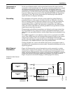
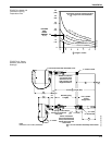
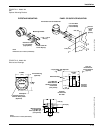
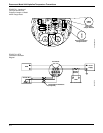
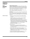
FIGURE 2-11. Model 444
with
Optional Mounting Bracket.
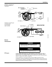
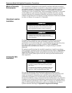
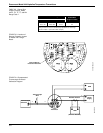
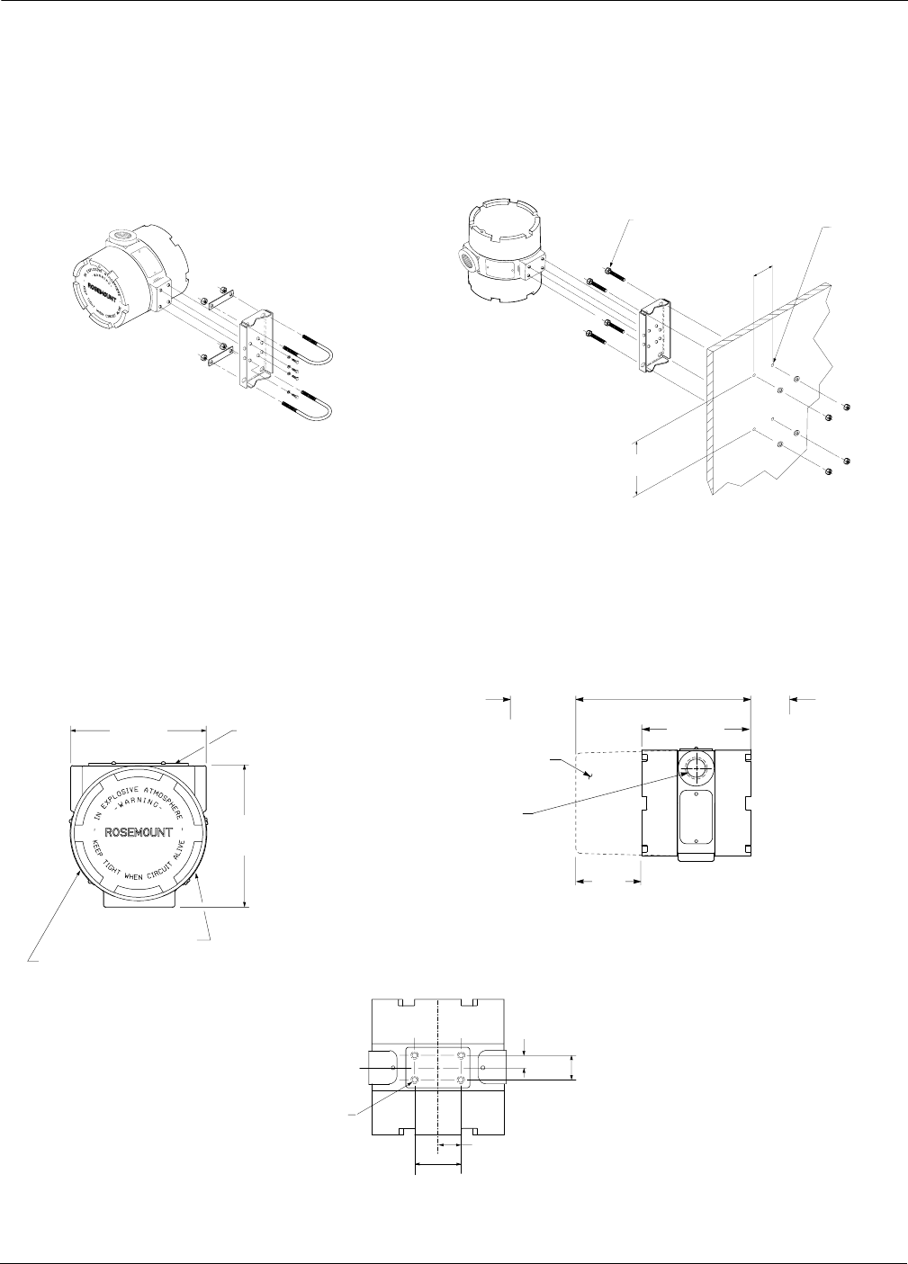
FIGURE 2-12. Model 444
Dimensional Drawings
Transmitter can be Rotated 90°
Clearance Hole
for ¼-inch Bolt
(eight places)
NOTE
Dimensions are in inches (millimeters).
Mounting Bracket
¼–20 ϫ½-inch
Bolt (4)
PIPESTAND MOUNTING
5
/16 –18 U-bolt for
2-inch Pipe (2)
5
/16 -inch Bolts
(four required,
not furnished)
Hole for
5
/16 -inch
Bolts
(four
places)
PANEL OR SURFACE MOUNTING
2.81 (81)
5.00 (127)
444-1151G, 1151F04A
NOTE
Dimensions are in inches (millimeters).
Permanent Tag
(Optional)
4.5 Max.
(114)
4.5 Max.
(114)
Explosion Proof or
Intrinsic Safety Label
(Optional)
Nameplate
Meter Housing
½–14 NPT per
ANSI C80.4 for
Conduit or Sensor
Connection
(two places)
7.5 (191) Max. with Optional
Meter
0.75 (19)
Clearance for
Cover Removal
(Typical)
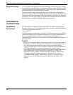
4.5 Max.
(114)
4.2
(117)
Terminal
Connections
this Side
Terminal
Circuitry
this Side
0.72 (18)
0.36 (9)
0.87 (22)
1.7
(44)
Mounting Holes
¼–20 UNC–2B
0.375 (10) Min. Dp.
(four places)
444-51LTE 05A, 51LTG 05A, 51LTF 05A