


Rosemount Model 444 Alphaline Temperature Transmitters
4-2
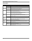
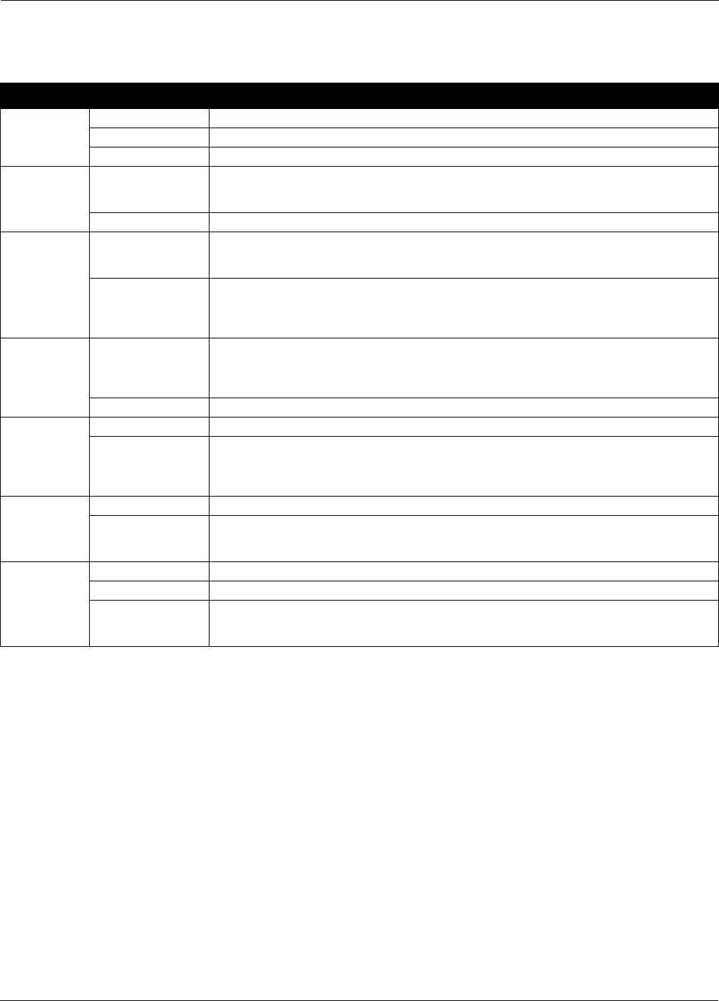
TABLE 4-1. Transmitter
Troubleshooting Symptoms
andCorrectiveActions.
Symptom Potential Source Corrective Action
High Output Sensor Check for a sensor or thermocouple open circuit. (RL, MV, T-Series with upscale burnout protection only)
Loop Wiring Check for dirty or defective terminals, interconnecting pins, or receptacles.
Electronics Assembly Check for dirty or defective interconnecting pins.
Erratic Output Loop Wiring Check for adequate voltage to the transmitter.
Check for intermittent shorts, open circuits, and multiple grounds.
Check for dirty or defective terminals or interconnection pins.
Electronics Assembly Check for dirty or defective interconnecting pins.
Low Output or
No Output
Sensor Check RTD leads to ensure that they are not shorting together or to ground. (RL only)
Check for correct RTD lead connection. (RL only)
Check for open RTD lead on double-lead side. (RL only)
Loop Wiring Check for adequate voltage to the transmitter. (RL only)
Check for intermittent shorts, open circuits, and multiple grounds. (MV, T series only)
Check for proper polarity at the signal terminal. (MV, T series only)
Check for dirty or defective terminals or interconnection pins.
Excessive
Current
(over 30 mA)
Loop Wiring Check for short between current signal leads.
Check to ensure that current signal leads ARE NOT connected to sensor terminals.
Check that sensor leads ARE NOT grounded when positive side of power supply is grounded (RL,
RL___B0912, LL, and LM)
Electronics Assembly Check for defective components in amplifier or current control section.
Excessive
Output Shift
with Ambient
Temperature
Sensor Check for incorrect thermocouple type or Incorrect thermocouple polarity connection (T series only)
Electronics Assembly Check to ensure that the burnout -protection jumpers positioned correctly (MV, T series only).
Check for defective components in voltage regulator or dc-to-ac converter section (MV, T series only).
Check for defective components in amplifier or current control section (all models).
May require replacement electronics assembly.
Unit Cannot be
Trimmed to
Desired Base
Temperature
Transmitter Check to ensure that unit is capable of desired range.
Electronics Assembly Check to ensure that the range board jumper is in the correct position.
Check to ensure that the burnout -protection jumpers positioned correctly. (MV, T series only).
Check for defective zero pot.
Unit Cannot be
Trimmed to
Desired Span.
Transmitter Check to ensure that unit is capable of desired range.
Loop Wiring Check for adequate voltage to the transmitter.
Electronics Assembly Check for defective components in amplifier or current control section.
Check for defective components in voltage regulator section.
Check for defective span pot.