44
5. In the "Multi-Radio" field of the PC programmer, select "Slave". Radio
Units are now ready for vehicle installation.
6. Program normally. Do not include Extended Option features.
INSTALLATION INSTRUCTIONS FOR
FRONT/REMOTE MOUNT DUAL RADIO
CONFIGURATION.
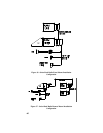
1. Plan the mounting locations of the two Radio Units. Note that the
maximum cable length allowed between the two radios is two meters.
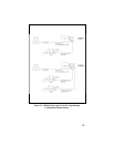
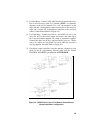
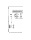
Referring to Figure 36, run Dual Radio Cable (19B802554P10) between
locations for Master and Slave Radio Units. Be sure to locate the P2/P3
connector assembly at the Master Radio Unit.
2. After installing Master Radio Unit mounting hardware, connect the
Dual Radio Cable Connector (P3) to the Master Radio Unit. Tighten
the two jackscrews on P3. Next connect the Accessory Cable
(19B802554P1 or P2) Connector (P1) to the Dual Radio Cable
Connector (P2), and tighten to jackscrews on P2.
3. Connect Microphone and Accessories. Refer to Accessory Installation
Manual for proper connection of Accessories.
4. Connect Power Cable, and Antenna, then install Master Radio Unit in
mounting bracket.
5. Connect "IGN A+" lead, if option is desired. Be sure internal Switch
SW601 is set properly. Refer to Page 20 of this manual for details.
6. After installing Slave Radio Unit in its mounting hardware, connect
Dual Radio Cable (P1), and tighten jackscrews. Be sure SW601 setting
on Slave Radio Unit is same as for Master Radio Unit. Connect Power
Cable and Antenna to Slave Radio.
7. Check Dual Radio operation, using Operator's Manual as test guide.
INSTALLATION INSTRUCTIONS FOR
REMOTE/REMOTE MOUNT DUAL RADIO
CONFIGURATION.
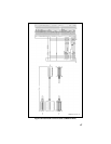
1. Plan the mounting locations of the two Radio Units. Note that the
maximum cable length allowed between the two radios is two meters.
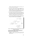
Referring to Figure 37, run Dual Radio Cable (19B802554P10) between
locations for Master and Slave Radio Units. Be sure to locate the P2/P3
connector assembly at the Master Radio Unit.


