


12
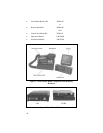
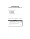
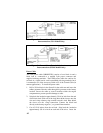
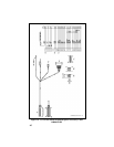
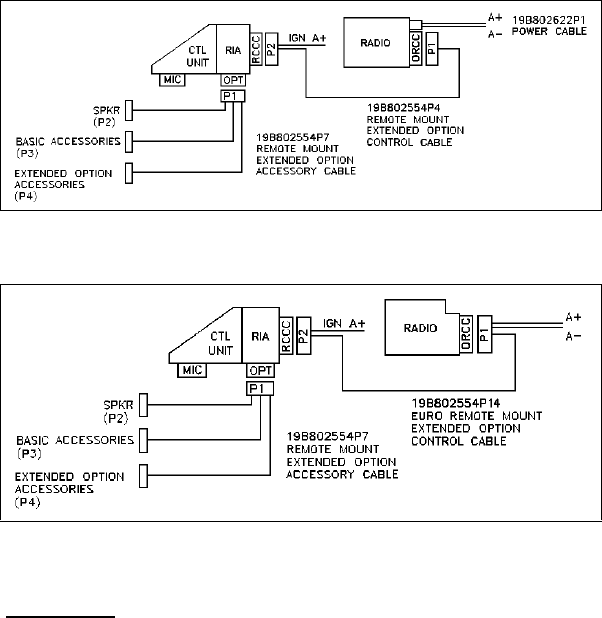
Figure 11 - Remote Mount Extended Option Accessory
Interconnections (USA Models Only)
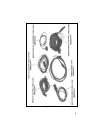
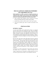
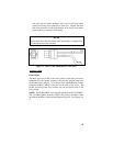
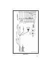
Figure 12 - Remote Mount Extended Option Accessory
Interconnections (EURO Models Only)
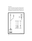
Power Cable
The USA power cable (19B802622P1) consists of a red lead A+ and a
black lead A- connected to a molded 2-pin power connector and
supplied with ring terminals. The EURO power cable also consists of a
red lead A+, a black lead A- and is terminated with ring terminals, but it
is connected to P1 of the Accessory Cable or P1 of the Control Cable (in
remote applications). To install the power cable:
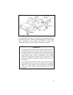
1. Drill a 5/8-inch hole in the firewall for the cable run and insert the
rubber grommet. Run the cable through this grommet to the battery
location. Secure the cable at several locations within the engine
compartment to prevent possible damage to cable.
2. Strip back the insulation approximately 3/8 of an inch from the end
of the black lead. Slide one of the large heat shrink sleeves onto the
wire and crimp a battery ring terminal onto this lead. Heat shrink
the sleeve over the crimp connection. Connect the black lead
directly to the battery negative (-) or ground frame member.
3. Cut off 12-18 inches from the red lead. Strip back the insulation
approximately 3/8 of an inch on each end of the wires. Insert the