


41
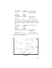
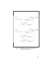
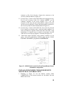
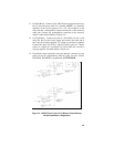
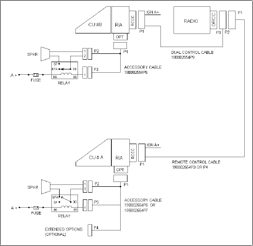
13. For Each Relay: Connect a #18 AWG black wire between the relay,
Pin 85 and accessory cable P3-1 (labeled “OUT2” on schematic
diagrams in the service manual). Use a 1/4” tab receptacle on the
relay side and a mating Molex connector and pins on the accessory
cable side. Connect the mating Molex connector to the accessory
cable P3 when finished (Refer to Figure 34).
14. For Each Relay: Connect one end of a #18 AWG red wire to the
relay, Pin 86. Cut the lead to length, and connect the other end to
the 1 amp fuse holder supplied. Use crimp on connectors supplied.
Connect the other side of the 1 amp fuse holder to the A+ battery
source or a vehicle A+ fuse block. Use a #18 AWG red wire and a
ring lug supplied, if needed (Refer to Figure 34).
15. Check dual control operation, using the operator’s manual as a test
guide. In the PC programming software, make sure the “DUAL
CONTROL SPEAKER is programmed ACTIVE HIGH.
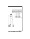
Figure 34 - ORION Dual Control Unit Remote Mount/Remote
Mount Installation Configuration