


39
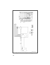
connector to Pin 30 of the relay. Connect the connector to the
Accessory Cable P2 (Refer to Figure 33).
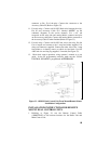
11. For each relay: Connect a #18 AWG black wire between the relay,
Pin 85 and Accessory Cable P3-1 (labeled “OUT2” on the
schematic diagrams in the service manual). Use a 1/4” tab
receptacle on the relay side and mating Molex connector and pins
on the accessory cable side. Connect the mating Molex connector to
the Accessory Cable P3 when finished (Refer to Figure 33).
12. For each relay: Connect a #18 AWG red wire to the relay, Pin 86.
Cut to length, and connect to the 1 amp fuse holder supplied. Use
crimp on connectors supplied. Connect the other side of the 1 amp
fuse holder to A+ battery source or vehicle A+ fuse block. Use #18
AWG red wire and ring lug supplied., if needed (See Figure 33).
13. Check dual control operation, using operator’s manual as a test
guide. In the PC programming software, make sure the “DUAL
CONTROL SPEAKER is programmed ACTIVE LOW.
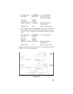
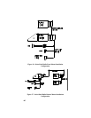
Figure 33 - ORION Dual Control Unit Front Mount/Remote Mount
Installation Configuration
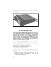
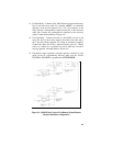
INSTALLATION INSTRUCTIONS FOR REMOTE
MOUNT DUAL CONTROL UNITS
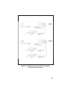
1. Referring to Figure 34, run the Remote Control Cable
(19B802554P3 or P4) between locations for the Radio Unit and
Main Control Unit.