


31
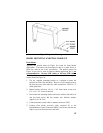
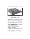
Cassette Assembly Mounting
1. Insert the cassette assembly in the mounting location. Secure the
cables with the sheet metal screws and retaining straps provided.
2. Secure the back of the cassette assembly using the mounting stud
(located at the back of the cassette assembly), No. 6 flat washer, No.
6 split lock washer and No. 6 wing nut.
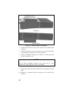
3. Several tabs are located on the top, bottom and sides of the cassette
assembly. These tabs are conveniently located near the front of the
assembly and may be bent out as needed to further secure the
cassette assembly to the vehicle.
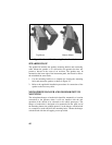
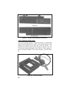
4. Next install the Handle Assembly:
a. Turn the radio upside down. Remove the two small machine
screws on the bottom of the radio, near the front. Use upward
pressure on screws to engage captivated threads for removal.
b. Using the machine screws and flat washers provided with the
handle assembly, attach the handle to the bottom of the radio.
The two holes on the handle should align with the two holes on
the radio created by step (a). Once installed, the rubber handle
should rotate freely from over top of the radio to just out in
front of the control unit (approximately 90 degrees). Be sure to
torque the two mounting screws within 6.5 to 8.25 in/lb limits.
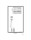
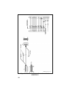
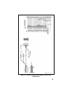
5. Connect the antenna coaxial cable to the cassette mounting
assembly rear connector.
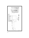
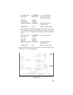
6. Connect the Power leads and the Ignition Sense leads as described
in previous sections. See Figure 29.
7. Connect the speaker cable connector P2 to the speaker and the basic
accessory connector P3 to the following options (if used, see Figure
29):
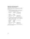
Option Plug & Pin
Ext. Hookswitch P3-3 (HOT)
P3-6 (GND)
Foot Switch P3-5 (HOT)
P3-2 (GND)
Horn Relay P3-1 (HOT)
P3-4 (GND)