


40
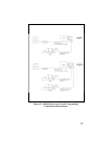
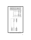
2. Run the Dual Control Cable (19B802554P9) between locations for
the Radio Unit and Auxiliary Control Unit. Be sure to locate the
P2/P3 connector assembly at the radio unit.
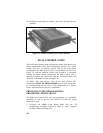
3. After installing the Radio Unit in the normal fashion, connect the
dual control cable connector (P3) to the Radio Unit. Tighten the two
jackscrews on P3. Next, connect the Remote Control Cable
connector (P1) to the Dual Control Cable connector (P2), and
tighten jackscrews on P2.
4. After installing the Main Control Unit in the normal fashion,
connect the Remote Control Cable (P2) to the Main Control Unit,
and tighten jackscrews.
5. After installing the auxiliary control unit in the normal fashion,
connect the Dual Control Cable (P1) to the Auxiliary Control Unit,
and tighten jackscrews.
6. Connect the accessory cable (19B802554P6) to the Auxiliary
Control Unit. Connect either the accessory cable (19B802554P6) or
the extended option accessory cable (19B802554P7) to the Main
Control Unit, as appropriate.
7. A yellow ignition sense lead is provided on each control cable. If
the “Ignition Sense” feature is enabled on the Radio Unit, it is
necessary to connect only one of the yellow leads provided,
whichever is convenient. Tape back the unused yellow lead. See
page 20 for details.
8. Install the speakers in convient locations near each control unit.
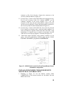
9. Install a relay (19A149299P1) from the kits supplied at a location
near the leads from each speaker. For mounting use the #8 X 3/4”
sheetmetal screw and nutplate supplied with each kit.
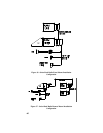
10. At a convenient point cut one of the wires in each of the 2-wire
speaker cables, spread the leads, and strip the ends. (Crimp a 1/4”
tab receptacle to each end.
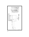
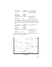
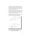
11. Main Control Unit Speaker: Connect the lead nearest the speaker
to Pin 87 of the relay. Connect the lead nearest the connector to Pin
30 of the relay. Connect connector to the accessory cable P2 (Refer
to Figure 34).
12. Auxiliary Control Unit Speaker: Connect the lead nearest the
speaker to Pin 87A of the relay. Connect the lead nearest the
connector to Pin 30 of the relay. Connect the connector to accessory
cable P2 (Refer to Figure 34).