


13
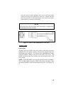
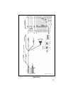
wire ends into the small openings at the end of each fuse holder
section and crimp a fuse connector to each wire. Prepare the other
end of the short wire in the same manner as in Step 2 and connect
to the positive (+) terminal of the battery.
NOTE
Do not install fuse into fuse holder until installation is completed and
all connections have been checked.
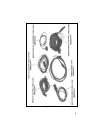
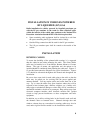
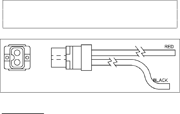
Figure 13 - Power Cable 19B802622P1 (USA Only)
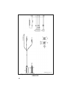
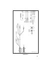
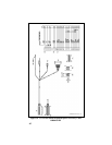
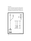
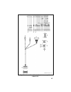
Accessory Cable
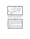
Front Mount
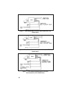
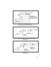
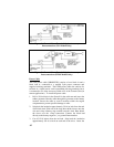
The Basic Accessory Cable, at one end, consists of the basic accessories
connector (P3), the speaker connector (P2) and the ignition sense lead.
At the other end is plug P1. P1 connects to the Option/Remote Control
Connector (ORCC) which is mounted on the back of the radio. The
EURO Accessory Cable also contains the red and black leads of the
Power Cable.
NOTE: The EURO ORCC is the opposite gender from the USA ORCC.
The Extended Option Accessory Cable is the same as the Basic Cable
but with the addition of the Extended Option Plug (P4). See Figures 14-
17.