


21
CAUTION
Certain problems may be encountered when accessory equipment is
connected to the ignition or accessory lines of the vehicle, where these
lines may have large filter capacitors and a leakage path present. If
the radio does not turn off within a reasonable amount of time after
the ignition is turned off, first try a different accessory or ignition
sense pick up point in the vehicle. Many vehicles have more than one
circuit that is switched by the ignition switch, and one may be
available that does not have large filter capacitors or a leakage path
present.
If a different pickup point cannot be found, then add a 470-ohm, 1-
watt resistor from the ignition sense pick point to ground. This will
discharge the capacitor(s) or reduce the leakage voltage to a low
value. Current drain through this resistor will be minimal (less than
0.03A) when the ignition is switched on.
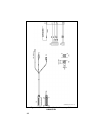
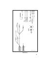
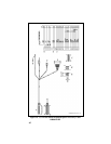
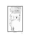
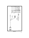
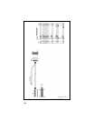
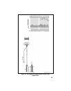
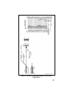
Control Cable (Remote Mount Only)
The Control Cable is used to connect the Control Unit (through the RIA)
to the Radio Transceiver in remote applications. Plug P2, at one end,
connects to the Remote Control Cable Connector (RCCC) which is
mounted on the back of the RIA. The Ignition Sense wire is also part of
P2. The other end of the Control Cable (P1) connects to the ORCC
which is mounted on the back of the radio. P1 of the EURO Control
Cable also contains the Power Cable leads. See Figures 20-23.
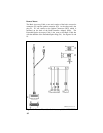
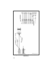
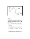
CONTROL UNIT MOUNTING (REMOTE
APPLICATIONS ONLY)
1. Using the bracket as a template, mark and drill the mounting holes.
Be sure to leave enough room at the rear of the control unit for the
cable connector. Refer to Figure 24 for control unit mounting
bracket installation.
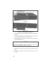
2. Secure the mounting bracket using the four No. 10 x 3/4 self-
tapping screws supplied (use No. 10 x 1-1/2 if needed.).
3. Secure the control unit to the bracket with the two 1/4-20 x 5/8 hex
head screws and lock washers provided.