


CHAPTER 3: Overview
23
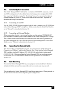
A-1
BUS A
BUS B
A-2
A-3 A-4 A-5
A-6
A-7 A-8
B-1 B-2 B-3 B-4 B-5
B-6 B-7
B-8
10/100 BaseT
ACT
A
B
ALARM
LINK
1
3
2
4
5
6
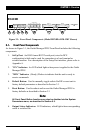
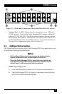
Figure 3-2: Back Panel Components (Model MPSH16-D20-120V Shown)
6. Network Port: An RJ45 Ethernet port for connection to your 100Base-T,
TCP/IP network. Note that the Outlet Managed PDU features a default IP
address (192.168.168.168). This allows you to connect to the unit without
rst assigning an IP address. Note that the Network Port also includes two,
small LED indicators for Link and Data Activity. For more information on
Network Port conguration, please refer to Section 5.9.
3.3. Additional Button Functions
The Default and Reset buttons on the Outlet Managed PDU front panel can be used
to perform the functions described below:
Notes:
• All Front Panel Button functions can also be disabled via the
System Parameters menu, as described in Section 5.3.
• When the Outlet Managed PDU is reset to factory defaults, all
user-defined configuration parameters will be cleared, and the
default "super" user account will also be restored.
1. Reboot Operating System:
a) Press and hold the Reset button for ve seconds, and then release it.
b) The Outlet Managed PDU will reboot it's operating system; all plugs
will be left in their current On/Off state.