


APPENDICES
189
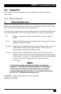
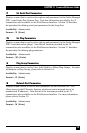
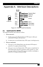
Appendix A. Interface Descriptions
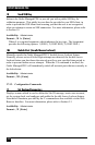
RJ-45
Pin No.
1
2
3
4
5
6
7
8
CTS
DCD
RXD
TXD
GND
DTR
RTS Request to Send
Ready Out
Data Out
Ground
Data In
Carrier Detect
Clear to Send
Pin 8
Pin 1
Figure A-1: RS232 Console Port Interface
A.1. Serial Console Port (RS232)
DCD and DTR hardware lines function as follows:
1. When connected:
a) If either port is set for Modem Mode, the DTR output at either port
reects the DCD input at the other end.
b) If neither port is set for Modem Mode, DTR output is held high (active).
2. When not connected:
a) If the port is set for Modem Mode, upon disconnect DTR output is
pulsed for 0.5 seconds and then held high.
b) If the port is not set for Modem Mode, DTR output is controlled by the
DTR Output option (Serial Port Parameters Menu, Option 23). Upon
disconnect, Option 23 allows DTR output to be held low, held high, or
pulsed for 0.5 seconds and then held high.