


CHAPTER 3: Overview
21
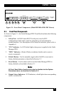
3.1. Front Panel Components
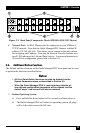
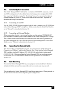
As shown in Figure 3.1, the Outlet Managed PDU Front Panel includes the following
components:
1. SetUp Port: An RJ45 format RS232 serial port (wired in DCE
conguration) which can be used for connection to a local terminal or
external modem. For a description of the Setup Port interface, please refer to
Appendix A.
2. "ON" Indicator: An LED which lights when power is applied to the Outlet
Managed PDU.
3. "RDY" Indicator: (Ready) Flashes to indicate that the unit is ready to
receive commands.
4. Default Button: Used to manually toggle outlets On/Off or reset unit to
factory default parameters as described in Section 3.3.
5. Reset Button: Used to reboot and/or reset the Outlet Managed PDU to
factory defaults as described in Section 3.3.
Note:
All Front Panel Button functions can also be disabled via the System
Parameters menu, as described in Section 5.3.
6. Output Status Indicators: LED indicators, which light when corresponding
outlet is switched On.
SETUP PORT
DEFAULT
OUTPUT STATUS
BRANCH A
CURRENT USAGE
RESET
ON RDY
A1 A2 A3 A4 A5 A6 A7 A8
B1 B2 B3 B4 B5 B6 B7 B8 10% 100%
BRANCH B
CURRENT USAGE
10% 100%
Outlet Managed
PDU
1 2 3 4
5
6 7
8
Figure 3-1: Front Panel Components (Model MPSH16-D20-120V Shown)