


FM Transmitters
60
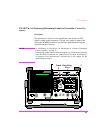
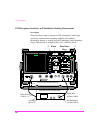
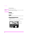
Measurement Procedure:
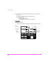
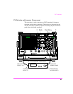
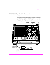
1 Connect the Transmitter Under Test as shown.
CAUTION: The RF present at the Test Set RF IN/OUT connector must not exceed 60W
continuous (or 100 Watts for 10 sec/minute).
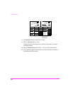
On the Test Set:
2 Press the PRESET key.
3 Press the TX key.
On the Radio:
4 Key the Transmitter and keep keyed until the remaining steps are complete.
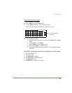
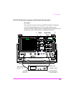
On the Test Set using the knob and data entry keys:
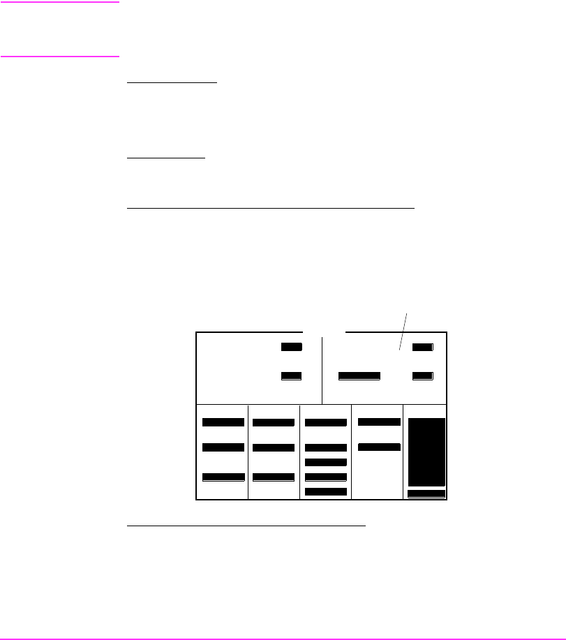
5 Set AFGen1 Lvl so that displayed FM deviation is 60% of the Transmit-
ter’s specified maximum frequency deviation (typically 3 kHz).
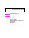
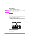
On the Test Set measured FM Deviation is displayed as shown.
To measure FM symmetry on the Test Set:
6 Set Detector to Pk−.
7 Record the displayed FM Deviation as Pk−.
8 Set Detector to Pk+.
Tune Mode
To Screen
TX TEST
FM Deviation
Auto/Manual
TX Frequency
TX Power
Tune Freq
145.280000
MHz
IF Filter
15 kHz
Input Port
RF in/Ant
AF Anl In
FM Demod
Filter 1
300Hz HPF
Filter 2
3kHz LPF
De-Emphasis
750 us/Off
Detector
Pk+-Max
Ext TX Key
On/Off
TX Pwr Zero
Zero
AFGen1 Lvl
-45.5
dBm
AF Freq
RF GEN
RF ANL
AF ANL
SCOPE
SPEC ANL
ENCODER
DECODER
RADIO INT
More
AFGen1 Freq
1.0000
MHz
kHz
kHz
W
kHz
Deviation
144.680040
0.591 1.00007
2.971