


The Test Set’s Features
41
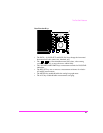
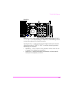
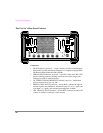
• EXT SCOPE TRIGGER INPUT Connector − female BNC connector to
input an external oscilloscope trigger. Maximum input level is ≈ 20 V peak.
• 10 MHz REF OUTPUT Connector − female BNC connector outputs a 10
MHz reference signal for locking external instruments.
• 10 MHz REF INPUT Connector − female BNC connector to input an
external 1, 2, 5, or 10 MHz reference signal.
• AUDIO MONITOR OUTPUT Connector − female BNC connector
provides an output from the AF Analyzer. Level is not affected by the
VOLUME control, but is affected by the SQUELCH control.
• Chassis Ground Terminal − provides a chassis connection. Also provides a
safety ground when DC power is used.
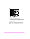
• RADIO INTERFACE Connector (optional) − 37 pin “D” style connector
for parallel and serial communications, and audio/transmitter control lines
between the Test Set and external radio equipment.
• DC INPUT Connector − 2-pin female connector to input 11-28 Vdc @
120W (maximum) for DC operation.
• AC INPUT Connector − 3-pin male connector to input 100 to 240 Vac for
AC operation.
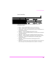
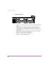
Key and Fuse Holders
•AC/DC− selects the instrument’s power source.
• DC FUSE Holder − 15A 250V fuse for DC operation.
• AC FUSE Holder − 5A 250V fuse for AC operation.