


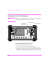
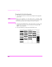


Preparing the Test Set for DC Operation
245
CABLING
RESTRICTIONS
When cabling the DC connector, remember that varying wire gauge,
type, and length will yield different resistive losses. Proper operation
of the Test Set requires that a minimum of 11 Vdc at 12 Adc be
present at the DC input connector. A typical DC connection should
consist of a cable made from 16 gauge stranded wire (20 feet in
length maximum) with a power source of 13.8 Vdc @ 15A.
4. Turn the POWER ON (in). After approximately 15 seconds, verify that the
CRT screen displays “All self tests passed” and that the “RX TEST” screen
is displayed.
If correct, the instrument is ready for operation.
NOTE: If DC power-up appears incorrect, turn OFF the POWER switch. Verify that
DC fuse is not blown. Replace if required.
Replacing a fuse with a different type, size, or rating than supplied with the
instrument can cause a fire hazard and/or electrical shock.