


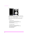


The Test Set’s Features
40
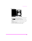
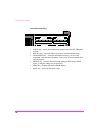
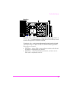
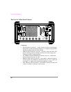
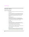
The Test Set’s Rear-Panel Features
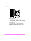
Connectors
• HP-IB Connector (optional) − 24-pin connector provides communication
between the Test Set and other instruments or a computer using the IEEE
488 Hewlett-Packard Interface Bus (HP-IB).
• SERIAL PORT Connector (optional) − 6-pin RJ-11 dual serial (RS-232C)
port for entering programs, printing test results and screen images, and
sending test results to external devices.
• DC CURRENT MEASUREMENT Terminals (optional) − dual banana
jacks to measure from 0 to +10 ADC.
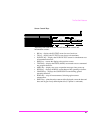
• MODULATION INPUT Connector − female BNC connector to input an
external signal to the modulators. Maximum input level is 12 V peak (full
scale input = 1 V peak), and nominal input impedance is 600Ω.
• CRT VIDEO OUTPUT Connector − female BNC connector provides CRT
video to an external “multisync” video monitor.
AC DC
DC INPUT
15A 11-32 VDC
DC
FUSE
AC FUSE
5A 250V
114.3
MHz
IF
IQ
RF IN
HEADPHONE
CW RF
IN
OPTION INTERFACE
CONTROL IO
AUDIO
MONITOR
10 MHz REF
INPUT
10 MHz REF
OUTPUT
EXT SCOPE
TRIGGER
CRT VIDEO
OUTPUT
MODUL ATION
INPUT
DC CURRENT
MEASUREMENT
SERIAL PORT
(OPTION)
HP-IB
(OPTIION)
PARALLEL PORT
(OPTIION)