Using the Oscilloscope
239
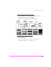
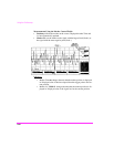
Measurement Using the Trigger Control Fields:
•From Controls select the desired trigger source:
• Internal uses the signal being displayed.
• Ext (TTL) uses the signal connected to the rear panel EXT SCOPE
TRIGGER INPUT connector.
• Encoder uses the optional signaling encoder.
• Trigger mode is selected as follows:
• In Auto, a trigger is automatically generated every 50ms (unless a
normal trigger is received).
• In Norm, a defined trigger required.
• In Cont, the oscilloscope sweeps on each trigger occurrence.
• In Single, the oscilloscope sweeps once on a trigger occurrence af-
ter Reset is selected.
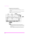
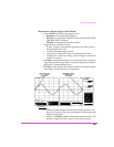
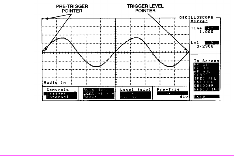
• Level (div) sets the internal trigger level (vertical divisions). Pos selects
triggering for positive going signals. Neg selects triggering for negative
going signals. Pointer indicates level.
• Pre-Trig sets the number of horizontal divisions to be displayed prior
to the trigger. Pointer indicates pre-trigger point.
Indicators:
•Marker Time ms changes the units that the marker position is dis-
played in. Displayed value is the time elapsed from the trigger point
to the current position.
•Marker Lvl V/kHz/% changes units that the marker position is dis-
played in. Displayed value is signal level at current position.


