


The Test Set’s Features
38
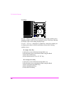
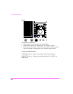
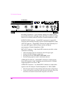
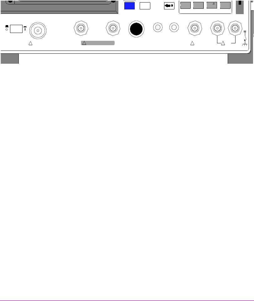
Connectors
RF IN/OUT Connector − type-N female connector for output signals
from the RF Generator, and input signals (60 Watts continuous, or 100
Watts for 10 sec/min) to the RF Analyzer. Nominal impedance is 50
Ω..
DUPLEX OUT Connector
− female BNC connector for output RF
Generator and Tracking Generator signals. Nominal impedance is 50Ω.
ANT IN Connector
− female BNC connector for input and analysis of
low-power RF signals (
≤200 m Watts), and for off-the-air
measurements. Nominal impedance is 50Ω.
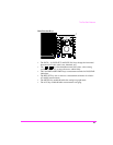
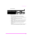
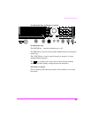
MIC/ACC Connector
− 8-pin female DIN connector provides various
connections including:
• Audio microphone input for modulation of the RF output signal
• Control of the RF Generator’s output state
• Switching between the TX TEST and RX TEST screens
• Provides keying signal to control a transmitter under test
AUDIO OUT Connector − female BNC connector to output signals
from AF Generators 1 and 2 (including encoder functions). Nominal
output impedance is%<1Ω at 1 kHz.
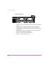
AUDIO IN Connectors
− two female BNC connectors to input audio
signals to the AF Analyzer. Nominal impedance is 1 M
Ω or 600Ω.
• HI is the signal input for both grounding and floating input configurations.
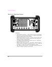
• LO may be selected to connect the signal reference to ground or float. The
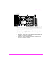
connectors and controls located on the rear panel are as follows:
CANCELSHIFT
Hz
µV
%
dBµV
ppm
W
ON/OFF
MEMORY
CARD
AUDIO IN
LOHI
!
MAX
42 v Pk
!
MAX
12 v Pk
AUDIO OUTSQUELCHVOLUMEMIC/ACC
MAX P OWER 20 0 mW
!
ANT IN
DUPLEX OUTRF IN/OUT
!
MAX POWER 60 W
CONTINUOUS
POWER
OFF ON