


OPERATION
Page
70
2001 Xantrex Technology, Inc.
5916 - 195th Street N. E.
Arlington, WA 98223
Telephone: 360/435-8826
Fax: 360/435-2229
www.traceengineering.com
SW Series Inverter/Charger
Part No. 2031-5
Rev. C: February 2001
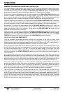
While connected to the utility, the battery charger will be engaged. Some applications may want to allow
the alternate power source (solar, wind or hydro) to recharge the battery instead of allowing the utility to
provide the power. The only option is to program the SET MAX CHARGE AMPS AC menu item under the
BATTERY CHARGING (10) menu heading to the minimum value, 1 amp AC, and set the BULK VOLTS
and FLOAT VOLTS settings, also under the BATTERY CHARGING (10) menu heading, to a low value.
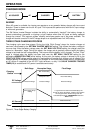
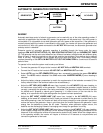
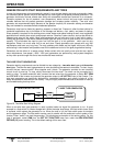
TRANSFER TIME
Normally there is no transfer time from the inverter to utility power or generator. The inverter operates in
parallel with the AC source at all times - even when battery charging. This allows the transfer from inverter
to the utility grid or generator to be interruption-free and virtually unnoticeable.
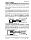
However, in SELL mode, when the utility grid fails, the inverter will reach the overcurrent protection
system setting (since it is will try to power everything that is connected to the grid). The inverter will
momentarily shut off while it opens the internal AC input relay. Once the relay has opened, the inverter will
begin to operate within a single cycle. This results in a 20 millisecond transfer period. Most AC loads,
including computers, will not be affected during the transfer.