


OPERATION
2001 Xantrex Technology, Inc.
5916 - 195th Street N. E.
Arlington, WA 98223
Telephone: 360/435-8826
Fax: 360/435-2229
www.traceengineering.com
SW Series Inverter/Charger
Part No. 2031-5
Rev. C: February 2001
Page
57
OPERATION
The SW Series Inverter/Charger can be configured as a simple stand-alone unit, working in conjunction
with your generator to handle loads too large for the generator alone, allowing two-wire or three-wire
generators to be turned on and off based on battery voltage or loads amp size, or functioning as a utility
interactive inverter which will allow you to send excess power back to the utility grid. Often, the inverter will
be set-up to operate in several modes at the same or different times - such as operating as an
inverter/charger in utility back-up mode with automatic generator control mode and generator support
mode during extended utility outage periods. The extensive configurations available are described in this
section will allow you to enhance and customize your inverter’s particular operation.
Before operating the SW Series Inverter/Charger, ensure that the unit is installed in accordance with the
instructions in the INSTALLATION section beginning on page 15.
THEORY OF OPERATION
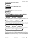
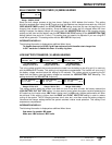
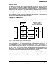
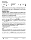
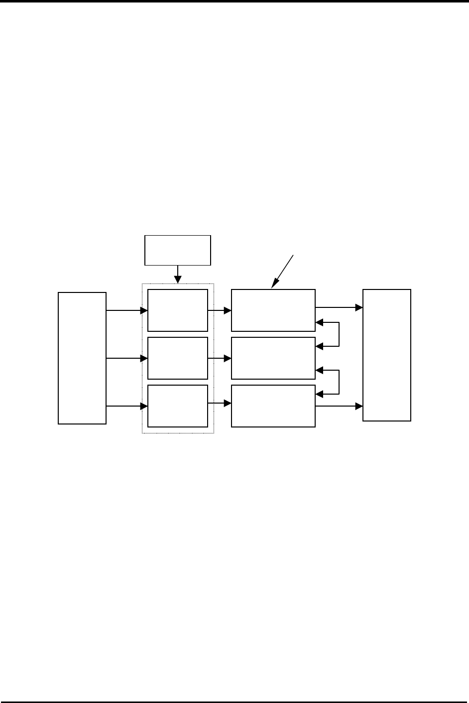
The SW Series inverters employ a new patented inverter design. This design uses a combination of three
transformers, each with its own low frequency switcher, coupled in series and driven by separate
interconnected micro-controllers. In essence, it is three inverters linked together by their transformers.
Figure 17, Trace™ SW Series Inverter Simple Block Diagram
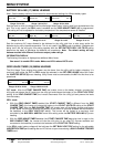
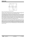
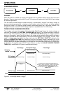
By mixing the outputs from the different transformers, a sine wave is produced. Shown in Figure 18, is the
output waveform from a Trace™ SW Series Inverter/Charger. Notice the “steps” form a staircase that is
shaped like a sine wave. The total harmonic distortion in this sine wave approach is typically 3-5%. The
multi-stepped output is formed by modulation of the voltage through mixing of the transformers in a
specific order. Anywhere from 34-52 “steps” per AC cycle are present in the waveform. The heavier the
load or lower DC input voltage the more steps there are in the waveform.
This type of inverter solves many of the problems associated with high frequency or ferroresonant sine
wave inverters. The low frequency method described has excellent surge ability, high efficiency (typically
85 to 90%), good voltage and frequency regulation, and low total harmonic distortion.
The inverter runs in two basic formats: as a stand-alone inverter (converting DC to AC), or as a parallel
inverter (with its output synchronized to another AC source). In inverter mode, only 60 Hz (50 Hz for export
units) waveforms are created. As the battery voltage rises, waveforms with progressively fewer steps are
generated. More steps are used when battery voltage decreases. Since the battery voltage tends to drop
with increased load, the waveform has increased number of steps with heavier AC loads.
AC
Loads
Battery
Low
Frequency
H-Bridge
Low
Frequency
H-Bridge
Transformer
Transformer
Transformer
Low
Frequency
H-Bridge
Bridges are “mixed” by
Micro-Controllers
Controlling the H-Bridges.
Micro-
Controllers