


INSTALLATION
2001 Xantrex Technology, Inc.
5916 - 195th Street N. E.
Arlington, WA 98223
Telephone: 360/435-8826
Fax: 360/435-2229
www.traceengineering.com
SW Series Inverter/Charger
Part No. 2031-5
Rev. C: February 2001
Page
19
Note: The three neutral terminals are common to each other and can be used in any combination or
order. In a residential application, it is often easier to only connect one AC neutral wire to the inverter and
make the other neutral connections at a central point such as in the AC load center, etc. In mobile
installations, the AC system must have the neutral physically isolated from the ground throughout the load
distribution powered by the inverter. The SW Series Inverter/Charger does not include neutral to ground
switching for the AC electrical system. This must be done externally from the inverter. See the NEUTRAL-
TO-GROUND BOND SWITCHING (RV AND MARINE APPLICATIONS) section on page 27 for more
information.
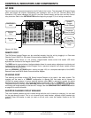
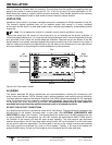
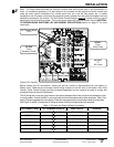
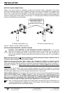
Figure 9, AC Input/Output Power Connection
Before making any AC connections, make sure that the inverter is disconnected from the battery (or
battery bank). Feed the wires through conduit fittings located on the left side or left bottom side of the
inverter. (Note: Conduit fittings must be purchased separately and are required by code to comply with
residential and commercial installations).
The AC wiring both in and out of the inverter must also be protected from short circuits and overloads by a fuse
or circuit breaker. Consult the NEC or your local code for more information and for other wire sizes. Table 13 on
page 132 gives suggestions for wire sizing. Follow the wiring guide on the circuit board inside the cover plate
(see Figure 9, above). Connect the AC wiring as follows (from front to back when wall mounted):
Table 1, AC Input and Output Wiring Connections
AC CONNECTIONS AC TERMINAL BLOCK # WIRE COLOR PURPOSE
AC HOT IN 1 1b Black (Hot) Utility Power
NEUTRAL IN 1 3b White (Neutral) Utility Power
AC HOT IN 2 2b Black (Hot) Generator
NEUTRAL IN 2 4b White (Neutral) Generator
AC HOT OUT 6b Black or Red (Hot) AC Loads
NEUTRAL OUT 5b White (Neutral) AC Loads
AC Terminal Block
(TB1)
AC IN 2
From
Generator Power
AC OUT
To
AC Loads
AC IN 1
From
Utility Power
1a
1b
2a
2b
3a
3b
4a
4b
5a
5b
6a
6b