


INSTALLATION
Page
24
2001 Xantrex Technology, Inc.
5916 - 195th Street N. E.
Arlington, WA 98223
Telephone: 360/435-8826
Fax: 360/435-2229
www.traceengineering.com
SW Series Inverter/Charger
Part No. 2031-5
Rev. C: February 2001
BATTERY CABLE CONNECTIONS
Cables must have crimped (or preferably, soldered and crimped) copper compression lugs unless
aluminum mechanical lugs are used. Soldered connections alone are not acceptable. We suggest using
high quality, UL-listed Xantrex battery cables. These cables are available in a specific assortment of sizes
from 1-½ to 10 feet, and in 2/0 or 4/0 AWG. They are color-coded and have pressure-crimped, sealed-ring
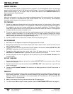
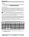
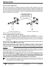
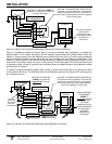
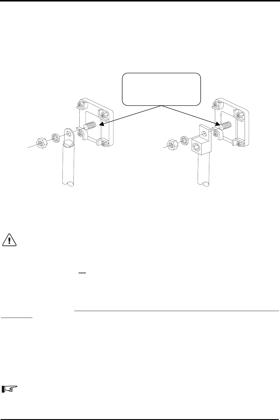
terminals. Contact your Xantrex dealer to order. Figure 11, illustrates proper method to connect the battery
cables to the SW Series Inverter/Charger.
Figure 11, Battery to Inverter Cable Connection
INSTALLATION PROCEDURE - BATTERY CABLES
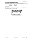
CAUTION: THIS INVERTER IS NOT REVERSE POLARITY PROTECTED. If the positive
terminal of the battery is connected to the negative terminal of the inverter and vice versa, the
result will be instantaneous failure of nearly every power transistor. This type of damage is
obvious and requires an extensive rebuilding of the inverter at your own cost. It is not covered by
the warranty.
Ensure that the inverter is off before connecting or disconnecting the battery cables and that all
AC power is disconnected from the inverter’s inputs.
Determine the correct size battery cable to use for your installation from Table 2, on page 22 and the
proper size disconnect/fuse from Table 3, Battery Cable To Maximum Breaker/Fuse Size on page 23.
Color-code the cables with colored tape or heat shrink tubing [the standard colors are red for positive (+)
and black for negative (-)]. Always double-check the polarity with a voltmeter before making the battery
connections
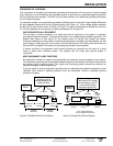
Install the over-current device (fuse or circuit breaker) between the inverter and battery - as close as
possible to the battery - in the ungrounded conductor [typically the positive (red) cable]. Connect a cable
from the battery negative terminal to the negative (black) terminal on the inverter.
Observe Battery Polarity! Place the battery cable ring terminals over the stud and directly against the inverter’s
battery terminals. Red is positive (+), Black is negative (-). Use a 1/2-inch wrench or socket to tighten the 5/16
SAE nut to 10-15 foot/pounds. Do not place anything between the cable ring terminal and the flat metal
part of the terminal or overheating of the terminal may occur. DO NOT APPLY ANY TYPE OF ANTI-
OXIDANT PASTE until after the battery cable wiring is tightened to 10–15 foot-pounds!
Note: Connecting the battery cables to the inverter battery terminals may cause a brief spark or arc
- usually accompanied by a "snapping" sound. This is normal - don’t let it scare you. It is simply the
internal capacitors of the inverter being charged.
2/0 Copper Compression Lug 2/0 Aluminum Mechanical Lug
Do not place anything
between battery cable lug
and terminal surface.
Assemble exactly as shown.