


TECHNICAL INFORMATION
Page
108
2001 Xantrex Technology, Inc.
5916 - 195th Street N. E.
Arlington, WA 98223
Telephone: 360/435-8826
Fax: 360/435-2229
www.traceengineering.com
SW Series Inverter/Charger
Part No. 2031-5
Rev. C: February 2001
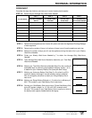
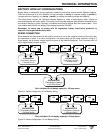
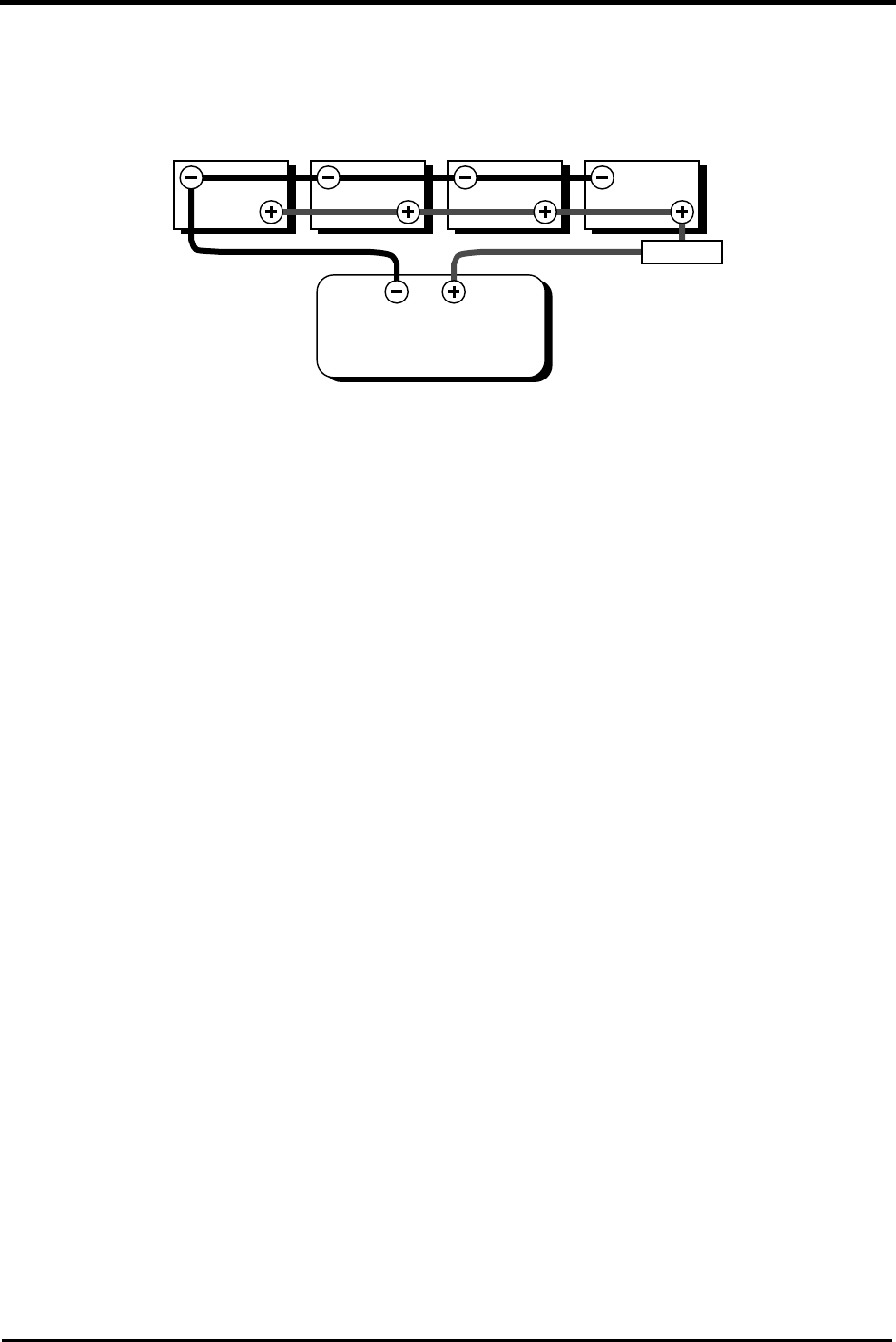
PARALLEL CONNECTION
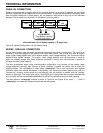
Batteries are connected in parallel when all the positive terminals of a group of batteries are connected
and then, separately, all the negative terminals are connected. In a parallel configuration, the battery bank
have the same voltage as a single battery, but an amp/hour rating equal to the sum of the individual
batteries. This is usually only done with 12-volt battery-inverter systems.
Each individual 12-volt battery capacity = 50 amp hours
Figure 33, Parallel Configuration: 12-Volt Battery Wiring
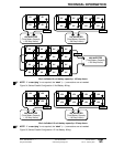
SERIES - PARALLEL CONNECTION
As the name implies, both the series and parallel techniques are used in combination. The result is an
increase in both the voltage and the capacity of the total battery bank. This is done very often to make a
larger, higher voltage battery bank out of several smaller, lower voltage batteries. This is common with all
battery-inverter system voltages. The smaller, lower voltage batteries are first connected in series to
obtain the needed voltage, then these ‘batteries, connected in series’ sets are connected in parallel to
increase the battery bank capacity.
The best arrangement when using a series-parallel configuration is to connect all the smaller, lower
voltage batteries in parallel, then connect all these ‘batteries in parallel’ into series sets to obtain the
needed voltage. This configuration is often called “cross-tying”. This is less convenient and requires
additional cables but reduces imbalances in the battery, can improve the overall performance and in a
“shorted cell” scenario, would cause only the battery(s) that are actually in parallel with the “shorted”
battery to discharge. This would allow you to re-configure your battery bank with the other batteries that
are in parallel with the shorted/discharged battery(s) and still be operational only at a lower capacity.
The more efficient “cross-tying” method is shown in Figure 34 and Figure 35 as “dash” (- - -) lines. If
“cross-tying” is not desired, the dash lines shown may be ignored.
12V 12V
12V INVERTER
(Total Battery Capacity
= 200 Amp Hours)
12V 12V
FUSED
DISCONNECT