


MENU SYSTEM
2001 Xantrex Technology, Inc.
5916 - 195th Street N. E.
Arlington, WA 98223
Telephone: 360/435-8826
Fax: 360/435-2229
www.traceengineering.com
SW Series Inverter/Charger
Part No. 2031-5
Rev. C: February 2001
Page
53
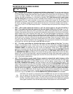
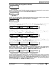
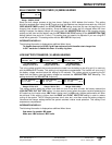
BULK CHARGE TRIGGER TIMER (15) MENU HEADING
Set Start Bulk
time 00:00
All Models
Range: 00:00 to 23:50
Starts the bulk charge process at the time shown. Setting to 00:00 defeats this function. This setting
should be enabled when using the SLT mode so that the batteries are charged once each day. With the
GRID USAGE TIMER enabled, the START BULK TIME setting should be set near the beginning of the
charging time window for best operation. Since the battery will usually be fully charged when this timer
setting is reached, the battery charger will usually reach the ABSORPTION stage of the charging process
quickly and will then hold the battery near the SET BULK VOLTS DC setting for the ABSORPTION TIME
setting (default time period is 2 hours). This setting does not need to be adjusted if you are using FLT
mode with a generator. This setting works with the AC1 HOT IN 1 input only.
INFORMATION DISPLAY
The following information is displayed as additional Menu Items.
To disable timer set to 00:00. If grid timer active set bulk time after start charge time.
In SLT mode don’t disable this timer. It is daily chg time.
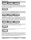
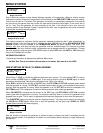
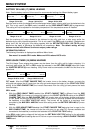
LOW BATTERY TRANSFER (16) MENU HEADING
Set Low Battery
Transfer VDC 11.3
Set Low Battery
Transfer VDC 22.6
Set Low Battery
Transfer VDC 45.2
12 VDC models
Range: 05.0 to 16.5
24 VDC models
Range: 10.0 to 33.0
48 VDC models
Range: 20.0 to 66.0
This is the voltage at which the inverter transfers the loads from the battery to the utility grid. It is used only
with the LBX and FLT modes. This setting is not temperature compensated. The transfer will occur only if
the battery voltage remains below this setting for 20 seconds. The system returns to powering the AC
loads from the battery once the battery voltage has reached the LOW BATTERY CUT IN setting. This
setting works with the AC1 HOT IN 1 input only.
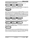
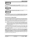
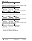
Set Low battery
cut in VDC 13.0
Set Low battery
cut in VDC 26.0
Set Low battery
cut in VDC 52.0
12 VDC models
Range: 05.0 to 16.5
24 VDC models
Range: 10.0 to 33.0
48 VDC models
Range: 20.0 to 66.0
This setting controls when the inverter turns back on once it has shut off when the battery reached the
LOW BATTERY CUT OUT VDC setting. It is also used to control when the system resumes powering the
AC loads from the inverter when LBX mode is being used. In LBX mode, the best performance will often
be achieved if this setting is higher than the BULK and FLOAT VOLTS DC setting in order to reduce
cycling of the system. The DC charging sources (wind, solar etc.) must then cause the battery voltage to
rise above the charger settings before the system resumes inverter mode operation. This setting is not
temperature compensated
INFORMATION DISPLAY
The following information is displayed as additional Menu Items.
See menu 9 to enable LBX mode.
Make sure LBX is above LBCO volts.