


TECHNICAL INFORMATION
Page
110
2001 Xantrex Technology, Inc.
5916 - 195th Street N. E.
Arlington, WA 98223
Telephone: 360/435-8826
Fax: 360/435-2229
www.traceengineering.com
SW Series Inverter/Charger
Part No. 2031-5
Rev. C: February 2001
BATTERY CABLE INDUCTANCE
When current passes through a conductor a magnetic field is set up around the conductor. As this
magnetic field builds, it induces voltage in any conductor that is close by, and it induces a voltage in the
original conductor. The voltage induced into the original conductor is called self-inductance, and tends to
oppose the current that produced it.
The magnitude of the self-induced voltage is proportional to the size of the loop formed by a wire. The
larger the loop, the larger the self-induced voltage. The positive and negative battery cables in a system
are in reality only a single circuit (wire), and so the inductance of the battery circuit depends on how the
cables are physically positioned or arranged with respect to one another.
If battery cables are separated by a distance, they have much more inductance than if they are close
together. If the two battery cables were coaxial there would be virtually no induced current flow since the
magnetic fields would cancel one another. However, we don’t have coaxial battery cables, but we can
approximate them by taping the cables together every four to six inches. When the cables are taped
together, the magnetic fields around each battery cable tend to cancel each other. When cables are
separated the magnetic fields add together and increase the inductance of the battery cables. If you aren’t
convinced that taping battery cables together helps reduce inductance, consider the following table of
information collected by Xantrex. We tested two sixteen foot long #4/0 AWG battery cables connected
together at one end and parallel to one another.
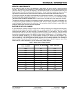
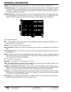
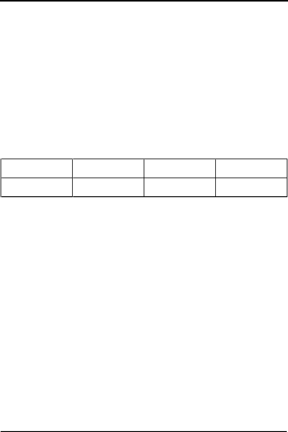
Table 8, Battery Cable Inductance
Distance Between
Battery Cables
Taped Together 12” Separation 48”+ Separation
Inductance
in micro-Henries
3.3 6.0 8-9
The above table shows that with only a foot of distance between the battery cables the inductance almost
doubles, and at four feet between cables the inductance is almost three times the inductance of cables
taped together.
Since the induced voltage in a conductor varies as the inductance times the rate of change of current in
the inductor, the induced voltage may be three times greater than it would be if cables were not taped
together. For more advanced readers, consider flyback effects and the induced voltage spikes can get into
the thousands of volts range if the battery were suddenly removed from the circuit (worst case).
These induced voltage changes cause ripple in the battery cables and must be absorbed or filtered by the
filter capacitors in the inverter. This ripple will lead to eventual premature breakdown of the filter capacitors
and performance loss in the inverter.
In addition to the problems mentioned, the induced current opposes the applied current (battery current)
which directly causes a loss of inverter performance as greatly reduced efficiency.
To avoid this problem, route your positive and negative DC cables in parallel, as close together as
possible. Secure the cables against movement with clamps or straps every 18 inches. Avoid routing
conductors near heat sources such as dry exhaust or furnace piping. Avoid chafing sources such as
steering cables, engine shafts, and throttle connections.
Hopefully this information gives a much more realistic and clear idea of why battery cables should be kept
short and close together. Maximum performance is the goal of any well designed power system and the
details such as this will help achieve the goal.