


MENU SYSTEM
Page
48
2001 Xantrex Technology, Inc.
5916 - 195th Street N. E.
Arlington, WA 98223
Telephone: 360/435-8826
Fax: 360/435-2229
www.traceengineering.com
SW Series Inverter/Charger
Part No. 2031-5
Rev. C: February 2001
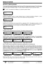
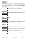
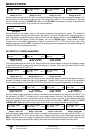
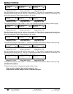
Set Max Charge
amps AC 20
Set Max Charge
amps AC 30
Set Max Charge
amps AC 15
Set Max Charge
amps AC 35
12 VDC models
Range: 01 to 25
24 VDC & 48 VDC models
Range: 01 to 35
“E & W” models
Range: 01 to 18
“J & K” models
Range: 02 to 40
Sets the maximum amount of AC input current that the battery charger will use to charge the battery. This
can be used to limit the charger output as well. The charger will “back-off” if the combination of AC loads
and the charger reaches the AMPS AC setting of the AC INPUT connected to prevent overloading the
source or tripping breakers. This process occurs automatically.
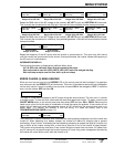
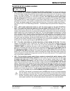
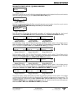
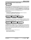
Set Temp Comp
LEADACID NICAD
All models
Allows selection of the battery type for the battery temperature compensation system. This effectively
reduces the battery charging set points when the battery is hot and increases them when the battery is
cold. The battery charging set points change ±0.005 volts per degree Celsius for the LEADACID setting
and ±0.003 volts per degree Celsius per battery cell for the NICAD setting. These battery setpoint
changes occur if the battery temperature is higher or lower than 25° C (77°F), and will only occur if the
battery temperature sensor (BTS) is installed. The setting should be changed from the default setting only
if NiCad or Nickel Iron batteries are used.
AC INPUTS (11) MENU HEADINGS
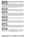
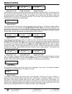
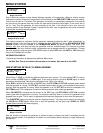
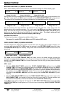
Set Grid (AC1)
amps AC 60
Set Grid (AC1)
amps AC 30.0
Set Grid (AC1)
amps AC 60
Standard models
Range: 00 to 63
“E & W” models
Range: 00 to 31.5
“J & K” models
Range: 00 to 63
This setting determines the level in AC amps at which the inverter begins to back-off the battery charger
or operates in parallel to reduce the load on the utility grid. Typically, this is set to the size of the AC circuit
breaker that feeds the AC HOT IN 1.
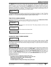
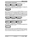
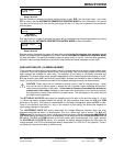
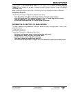
Set Gen (AC2)
amps AC 30
Set Gen (AC2)
amps AC 15.0
Set Gen (AC2)
amps AC 30
Standard models
Range: 00 to 63
“E & W” models
Range: 00.0 to 31.5
“J & K” models
Range: 00 to 63
This setting determines the level in AC amps at which the inverter begins to back-off the battery charger or
operates in parallel to reduce the load on the generator. Typically, this is set to the size of the generator’s
circuit breaker feeding the inverter (AC HOT IN 2) or the maximum output amperage ability of the generator.
Set Input Lower
limit VAC 108
Set Input Lower
limit VAC 206
Set Input Lower
limit VAC 88
Set Input Lower
limit VAC 196
Standard models
Range: 80 to 111
“E” models
Range: 170 to 220
“J & K” models
Range: 70 to 90
“W” models
Range: 160 to 210
Sets the lowest voltage at which the inverter is allowed to be connected to the utility grid (AC INPUT 1) or
the generator (AC INPUT 2). When the AC input voltage reaches this level, the inverter will stop battery
charging and begin to invert in parallel with the AC source to reduce the load. If the voltage continues to
drop, the inverter will disconnect and will power the loads from the battery. NOTE: Typically the INPUT
LOWER LIMIT VAC setting will be based upon the minimum AC voltage tolerable by the AC loads.
Set Input Upper
limit VAC 132
Set Input Upper
limit VAC 254
Set Input Upper
limit VAC 112
Set Input Upper
limit VAC 244
Standard models
Range: 128 to 149
“E” models
Range: 250 to 298
“J & K” models
Range: 105 to 129
“W” models
Range: 240 to 288
Sets the highest voltage at which the inverter is allowed to be connected to the utility grid (AC INPUT 1) or
generator (AC INPUT 2). This is also the maximum voltage at which the inverter will sell power into the line if
SELL is enabled. When this voltage is reached the inverter will disconnect and power the AC loads from the
battery. If this voltage drops below this setting, the inverter will reconnect the loads to the AC source.