


MENU SYSTEM
Page
40
2001 Xantrex Technology, Inc.
5916 - 195th Street N. E.
Arlington, WA 98223
Telephone: 360/435-8826
Fax: 360/435-2229
www.traceengineering.com
SW Series Inverter/Charger
Part No. 2031-5
Rev. C: February 2001
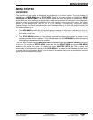
METERS (4) MENU HEADING
The current meters provided measure only the real, in phase component of the current. This is the portion
of the power that actually uses power from the battery. This allows better estimation of the DC power
drawn by the load or the battery charger. This may cause the reading to vary from other AC meters.
NOTE: The meters do not display a (+) symbol for positive values.
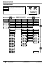
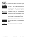
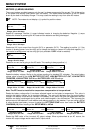
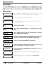
Inverter/charger
Amps AC 00
All models
Range: -64 to +64 Amps
Reads AC amperage. Positive (+) amps indicates inverter is charging the batteries. Negative (-) amps
indicate the inverter is powering the AC loads and the batteries are being discharged.
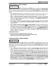
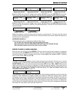
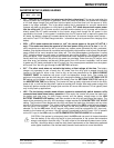
Input
Amps AC 00
All models
Range: -64 to +64 Amps
Reads total AC input current from the grid (AC1) or generator (AC 2). The reading is positive (+) if the
inverter is drawing power from the utility grid to charge the battery or power AC loads and negative (-) if
the inverter is selling power into the utility grid (only available if SELL mode is enabled).
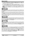
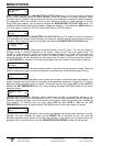
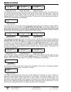
Load
Amps AC 00
All models
Range: 00 to 64 Amps
Reads the current that is going to the AC loads. This reading is always positive (+).
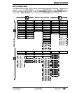
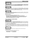
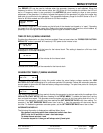
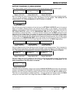
Battery actual
volts DC 12.6
Battery actual
volts DC 25.2
Battery actual
volts DC 50.4
12 VDC models
Range: 5.0 to 17.5 VDC
24 VDC models
Range: 10.0 to 35.5 VDC
48 VDC models
Range: 20.0 to 71.0 VDC
Reads the battery voltage. Similar to the voltage reading of a standard DC voltmeter. The actual battery
voltage value is used for the LOW BATTERY CUT OUT; HIGH BATTERY CUT OUT, LOW BATTERY
TRANSFER, LOW BATTERY CUT IN and BATTERY SELL VOLTS settings.
Battery TempComp
volts DC 12.6
Battery TempComp
volts DC 25.2
Battery TempComp
volts DC 50.4
12 VDC models
Range: 5.0 to 17.5 VDC
24 VDC models
Range: 10.0 to 35.5 VDC
48 VDC models
Range: 20.0 to 71.0 VDC
Note: The BTS must be installed for temperature compensation to be operational.
Reads the battery voltage after it has been adjusted based on the battery’s temperature. This value is
used by the battery charger for its regulation settings. The value will decrease from the actual battery
voltage if the battery is cold and will increase if the battery is hot, which may give the appearance that the
batteries are being overcharged during winter and undercharged in the summertime. This improves the
performance of the batteries in cold weather and reduces gassing in hot weather. If you are using a NiCad
or other alkaline type battery, be sure to adjust the SET TEMP COMP menu item under the BATTERY
CHARGING (10) menu heading of the SETUP MENU to NiCad.
Inverter
volts AC 120
Inverter
volts AC 230
Inverter
volts AC 105
Inverter
volts AC 220
Standard models
Range: 00 to 255 VAC
“E” models
Range: 00 to 510 VAC
“ J & K” models
Range: 00 to 255 VAC
“W” models
Range: 00 to 510 VAC
Reads the RMS value of the inverter’s AC output voltage. When synchronized to an AC source, the
inverter AC output voltage would match the AC inputs value.