


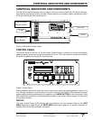

CONTROLS, INDICATORS AND COMPONENTS
2001 Xantrex Technology, Inc.
5916 - 195th Street N. E.
Arlington, WA 98223
Telephone: 360/435-8826
Fax: 360/435-2229
www.traceengineering.com
SW Series Inverter/Charger
Part No. 2031-5
Rev. C: February 2001
Page
11
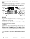
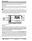
AC1 IN GOOD (Green)
Indicates that AC power is present at the AC HOT IN 1 and NEUTRAL IN 1 input terminals. This input is
intended for utility power. When an AC source is connected to the input terminals, it will start to blink slowly
(once a second) to show the AC voltage has been detected. After the inverter has connected to the AC
source, the LED will be solid. If the LED starts to blink during operation, utility power has been dropped.
AC2 IN GOOD (Green)
Indicates that AC power is present at the AC HOT IN 2 and NEUTRAL IN 2 input terminals. This input is
intended for generator power. When an AC source is connected to the input terminals, it will start to blink
slowly (once a second) to show the AC voltage has been detected. After the inverter has connected to the
AC source, the LED will be solid. If the LED starts to blink during operation, generator power may have been
dropped.
This LED will also blink slowly (once a second) when the automatic generator control system is enabled.
When the generator has started, it will continue to blink slowly until the generator has been connected. If the
generator does not successfully start, the AC 2 IN GOOD LED will stop blinking and the red ERROR LED will
turn on. The ERROR CAUSES (5) menu heading will indicate a GENERATOR SYNC ERROR condition.
BULK (Yellow)
This indicator will be on to indicate the inverter is in the Bulk or Absorption charge stage. This indicator will
go off and the FLOAT indicator will illuminate when the battery voltage has been held near the SET BULK
VOLTS DC setting for the time period determined by the SET ABSORPTION TIME setting from the
BATTERY CHARGING (10) menu heading.
If the EQ mode is selected from the SET GENERATOR menu item under the GENERATOR MODE (2)
menu heading, the BULK LED will slowly blink while the charger completes the equalization process.
FLOAT (Green)
This indicator will be on when the battery voltage has reached the Float Stage of the charging process. It
will now regulate the charging process to the SET FLOAT VOLTS DC setting from the BATTERY
CHARGING (10) menu heading. The SET FLOAT VOLTS DC setting provides a maintenance charge to
the battery until another Bulk Charge Cycle is initiated or the AC source is disconnected. If a generator is
manually controlled and powering the battery charger, the FLOAT indicator will come on to indicate that
the generator should be turned off, since the battery is now fully charged.
This indicator is also used to indicate the regulation setpoint when the inverter is operating as an Utility
Interactive Inverter (SELL mode). The indicator will blink slowly to indicate the battery is regulated to the
SET BATTERY SELL VOLTS DC setting from the BATTERY SELLING (17) menu heading, and the
indicator will be “solid” to indicate the battery is regulated to the SET FLOAT VOLTS DC setting from the
BATTERY CHARGING (10) menu heading.
ERROR (Red)
Indicates that an operating error has occurred (refer to the ERROR CAUSES (5) menu heading for a list
of possible causes). To reset the inverter, press the red ON/OFF MENU button and then select OFF and
then ON with the SET POINTS buttons or by pressing the red button several times.
This indicator will blink slowly to indicate that the AC source frequency is not well-adjusted (3 to 7 hertz
from nominal). You can use the LED blink to help adjust the AC source frequency. Once the frequency is
within 3 hertz of your nominal frequency, the LED will turn off.
OVERCURRENT (Red)
The load requirement has exceeded the inverter’s maximum output AC amps. A sustained overcurrent
condition will require a manual reset by pressing the red ON/OFF MENU button and then selecting OFF
and then ON with the SET POINTS buttons or by pressing the red button several times. Momentary
flashing of the red OVERCURRENT indicator means that the inverter has reached it maximum output AC
amps and has automatically reset itself. This may occur during motor startups and is acceptable.