


CONTROLS, INDICATORS AND COMPONENTS
Page
14
2001 Xantrex Technology, Inc.
5916 - 195th Street N. E.
Arlington, WA 98223
Telephone: 360/435-8826
Fax: 360/435-2229
www.traceengineering.com
SW Series Inverter/Charger
Part No. 2031-5
Rev. C: February 2001
AC SAFETY GROUND
The AC Safety Ground is used to connect the inverter chassis to the AC Grounding System.
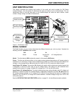
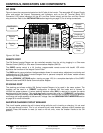
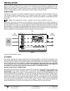
AUXILIARY AND GENERATOR CONTROL RELAY CONNECTORS
Figure 6, Auxiliary and Generator Control Relay Connectors
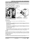
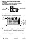
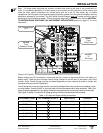
DC SIDE
Figure 5 shows the components located on the DC side of the inverter. Refer to the INSTALLATION
section for the battery wiring connections to the Battery Terminals and the DC Ground.
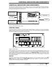
Figure 7, DC Side
BATTERY TERMINALS
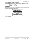
Caution: Before connecting the battery cables to the inverter, verify the correct battery voltage
and cable polarity using a voltmeter. The inverter is not reverse polarity protected. If the
positive terminal of the battery is connected to the negative terminal of the inverter and
vice versa, severe damage will result. If necessary, color-code the cables with colored tape or
heat shrink tubing: RED for positive (+); BLACK for negative (-) to avoid polarity problems.
DC (EQUIPMENT) GROUND
This connection is used to connect the exposed chassis of the inverter to the DC grounding system. The
terminal accepts wires from #14 AWG to #2 AWG.
Auxiliary Control
Relay Connectors
Generator Control
Relay Connectors
Battery
Terminal
(-)
Battery
Terminal
(+)
DC
(Equipment)
Ground