Operating Basics
1-10 AFG3000 Series Arbitrary/Function Generators Reference Manual
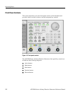
BNC Connectors
Refer to Figure 1-2 on page 1-2 for the locations of the front panel BNC connec-
tors.
CH1 Output. This BNC connector will output the Channel 1 signal. This connector
will be deactivated when the Channel 1 output button is not selected. The load
impedance for this connection can be set in the Output Menu.
CH2 Output. Same functionality as Channel 1 Output. This output is not present in
the single channel instrument model.
Trigger Output. This connector provides a TTL level pulse synchronized with the
Channel 1 output. The connector provides a signal that will allow an oscilloscope
to synchronize with the arbitrary/function generator.
When you synchronize multiple arbitrary/function generators, the Trigger Output
on the master instrument is connected to the Trigger Input of the slave instrument.
Trigger Input. When the arbitrary/function generator is a slave to another device,
The Trigger Input connector will be used to synchronize the arbitrary/function
generator with the master device. Trigger signals from other devices can also be
input here.
USB Memory
The USB Memory connector is a host connector, which allows a USB client
memory device to be connected. You can perform the following tasks:
Save or recall user-defined waveforms to/from a USB memory
Save or recall setups to/from files on a USB memory
Update your arbitrary/function generator firmware
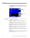
To Unlock Front Panel
Controls
The front panel may be locked by a remote user while the instrument is being
remotely controlled via GPIB, USB or Ethernet. When the front panel is locked, all
keys and buttons are disabled except the power switch. The “Lock” symbol at the
top right of the screen indicates that the instrument front-panel controls are locked.
To unlock the front-panel, use the remote command or push the front-panel Cancel
button twice in a row. This method is not applied if the arbitrary/function generator
is in the GPIB LLO (Local Lockout) state.
CAUTION. Do not remove USB memory while writing or reading data. It may cause
data loss and the USB memory may be damaged.
Before reinsert a USB memory after removing it from the instrument, wait at least
one second.
Do not repeat insertion and removal of USB memory without waiting one second
each time to avoid damage to the instrument.


