


Black 0008
Black0008
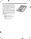
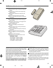
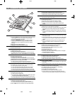
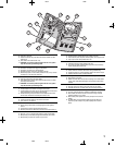
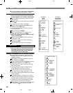
4. CONSOLE FEATURES
1 24-HOUR BUTTONS
★
Pressing the [
FIRE
] button for two seconds sounds the fire siren and sends
a “fire” message to a central monitoring station through the digital
communicator (if the system is monitored).
★
Pressing the [
EMERGENCY
] button for two seconds sounds the
emergency siren and sends an “emergency” message to a central
monitoring station through the digital communicator (if the system is
monitored).
★
Both work even when system is disarmed.
★
IMPORTANT: For personal emergency use only.
2MODE BUTTONS
★
Used to control the Console.
OFF
★
Off Mode disarms the system.
★
Switching to Off Mode stops the alarm siren.
✔
Multiple beeps sound and status lights flash if an alarm has occurred.
☞
Multiple beeps mean caution. AN INTRUDER MAY STILL BE PRESENT.
CHIME
★
Chime Mode disarms the system.
★
Switching to Chime Mode stops the alarm siren.
✔
Multiple beeps sound and status lights flash if an alarm has occurred.
☞
Multiple beeps mean caution. AN INTRUDER MAY STILL BE PRESENT.
★
Chime Mode is for monitoring doors and windows.
✔
Use this mode as an “automatic door chime” when at home.
✔
Opening any protected door or window causes Console to “ding-dong”.
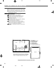
HOME
★
Home Mode arms the perimeter sensors, but not the interior sensors.
✔
Use this mode when anyone is staying behind.
✔
Interior motion detectors and interior door sensors are not armed.
✔
Home secure mode makes all delayed perimeter sensors instant.
✔
Secure exit mode starts an exit delay while remaining in Home Mode.
✔
Re-entering during the exit delay restarts the exit delay (one time only).
AWAY
★
Away Mode arms the entire system.
✔
Use this mode when leaving home.
✔
Door sensors set for “delayed” will have a delay that allows you to leave
and enter the premises without sounding the alarm.
✔
Re-entering during the exit delay restarts the exit delay (one time only).
✔
Entry Delay beeps warn you to disarm the system before the siren starts.
TEST
★
Test Mode is for testing the system sensors.
✔
All sensor status lights blink when the Test Mode is entered.
✔
Each sensor status light will stop blinking when its sensor is tested.
★
Hold the [
TEST
] button down to test all of the Console’s indicator lights.
3 MODE INDICATORS
★
Specific indicator will light showing the mode the Console is in.
★
HOME indicator will blink during secure exit and home instant modes.
★
AWAY indicator will blink during the exit delay in the Away Mode.
4 CONSOLE STATUS INDICATORS
★
Show the current status of the Console.
POWER LIGHT
★
Glows when AC power is on.
★
Dims when AC power is off and backup battery is installed.
★
Blinks when the backup battery is low, recharging or missing.
★
Off when AC power is off and no backup battery is installed (system
disabled).
BATTERIES LIGHT
★
Blinks when one or more sensors has a low battery.
★
Press [
∗
] key for two seconds to view sensor status. Sensor status indicator
for any sensor with a low battery will light along with the BATTERIES
indicator.
★
Switch to Test Mode after replacing the sensor battery and completely test
the system (see Test Mode). Switching to Test Mode clears the low battery
indication.
TROUBLE LIGHT
★
Blinks when one or more sensors have not reported status during the eight
hour status time window.
★
Press [
∗
] key for two seconds to view sensor status. Sensor status indicator
for any sensor that has not reported in will light along with the TROUBLE
indicator.
★
Switch to Test Mode after servicing the sensor and completely test the
system (see Test Mode). Switching to Test Mode clears the trouble
indication.
5 SIREN SPEAKER
★
Makes unique sounds for burglary, fire and emergencies.
★
Alarm sirens stop automatically after five minutes.
★
Sounds advisory tones to confirm keystrokes from the Console.
★
Sounds mode selections tones.
★
Sounds alarm memory tones.
★
Beeps when Automation Output is activated.
★
Speaks the system status information when optional VB-2 or VB-3 digital
voice synthesis module is installed.
★
Terminals available for an external siren.
6 STATUS INDICATORS
★
Indicates the status of each of the system’s sensors.
★
Lights show which doors and windows are open.
★
Lights flash to display sensors that have caused an alarm.
★
Stick-on labels are provided to identify the custom sensor locations.
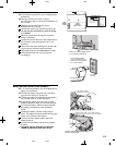
7 CASE ACCESS SCREW (HIDDEN)
★
Remove clear display window and sensor identification card to gain access
to the screw.
★
Remove case access screw to unlock case. Case hinges open to the left.
8 KEYPAD
★
Backlit keys for easy viewing in low light conditions.
★
For entering the user’s user code (numerically or alphabetically).
★
Used when programming system options.
★
Press [
(A)
] key to activate Automation Output.
★
Press the [
∗
] key to clear keypad if the wrong key is pressed.
★
Press and hold the [
∗
] key for one second to view sensor battery and
supervisory status (see BATTERIES and TROUBLE indicator description).
1
2
3
4
5
6
7
8
6