


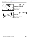
29
Section 4: Maintenance & Lubrication
5/09/08
RCR2596, RCR2510 and RCRM2510 Rotary Cutters 312-753M
Land Pride
Table of Contents
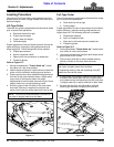
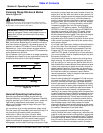
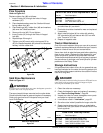
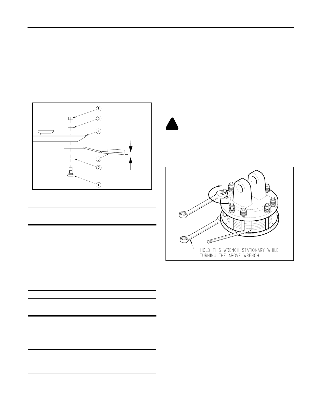
9. Check blade deflection. If deflection is greater than
3/4", remove blade bolt and reassemble as before
except include shim (#2) in the assembly. Select
shim thickness based on deflection. The greater the
deflection, the thicker the shim.
10. Once blade deflection is correct, replace used nut
with new locknut (#6) and torque to 450 ft-lbs.
11. If replacing dishpan (#4), nut on gearbox output shaft
should be torqued to 450 ft-lbs. minimum and cotter
pin installed in nut with legs securely bent around
nut.
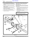
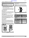
Cutter Blade Assembly
Figure 4-2
3/4" maximum
blade deflection
when blade
bolts are tight
Land Pride Cutter Blade Parts
Item Part No. Part Description
318-586A BLADE BOLT KIT
(Includes items 1, 2, 5, & 6 below)
1 802-277C BLADE BOLT 1 1/8-12 x 3 7/16 WITH KEY
2 312-075D BLADE SPACER 16 GA. (.060")
2 312-082D BLADE SPACER 18 GA. (.048")
2 312-089D BLADE SPACER 20 GA. (.036")
2 312-808D BLADE SPACER 24 GA. (.024")
3 --------- SEE LIST OF CUTTER BLADES BELOW
4 312-881H 27 x 10G OVAL DISHPAN WELDMENT
5 804-147C WASHER FLAT 1 HARD ASTMF436
6 803-170C NUT HEX TOP LOCK 1 1/8-12 PLATE
Land Pride List of Cutter Blades
Part No. Part Description
820-195C RCR2596 CUTTER BLADE 1/2 x 4 x 20 CCW
820-196C RCR2596 CUTTER BLADE 1/2 x 4 x 20 CW
820-137C RCR2510 CUTTER BLADE 1/2 x 4 x 25 CCW
820-112C RCR2510 CUTTER BLADE 1/2 x 4 x 25 CW
Optional Low Lift Cutter Blades
820-210C RCR2596 BLADE 1/2X4X20.5 LL CCW
820-211C RCR2596 BLADE 1/2X4X20.5 LL CW
820-193C RCR2510 BLADE 1/2X4X25 LL CCW
820-209C RCR2510 BLADE 1/2X4X25 LL CW
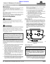
Driveline Protection
Cutter drive components are protected from shock loads
by a friction slip-clutch. The clutch must be capable of
slippage during operation to protect the gearbox,
driveline and other drive train parts.
Clutch Run-In
Friction clutches should be “run-in” prior to initial
operation and after long periods of inactivity to remove
any oxidation that may have accumulated on friction
surfaces. To prevent driveline and gear box damage,
repeat “run-in” instructions at beginning of each season
and when moisture and/or condensation seizes inner
friction plates.
!
CAUTION!
Engage parking brake, disengage PTO, shut off tractor, and
remove key before making any of the following adjustments.
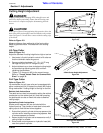
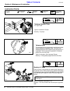
Refer to Refer to Figure 4-3:
1. Using a pencil or other marker, scribe a line across the
exposed edges of the clutch plates and friction discs.
Clutch
Figure 4-3
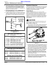
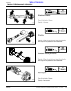
2. Carefully loosen each of the 8 spring retainer nuts on
the clutch housing a total of EXACTLY 2 revolutions.
It will be necessary to hold the hex end of the retainer
bolt in order to count the exact number of revolutions.
3. Start tractor and engage driveline for 2-3 seconds to
permit slippage of the clutch surfaces. Disengage
the PTO, then re-engage a second time for 2-3
seconds. Disengage the PTO, shut off tractor and
remove key. Wait for all components to stop before
dismounting from tractor.
4. Inspect clutch and ensure that scribed markings
made on the clutch plates have changed position.
Slippage has not occurred if any two marks on the
friction disc and plate are still aligned.
13693