


11
Section 1: Assembly and Set-Up
5/09/08
RCR2596, RCR2510 and RCRM2510 Rotary Cutters 312-753M
Land Pride
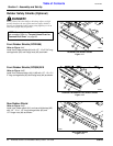
Table of Contents
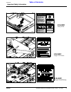
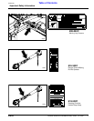
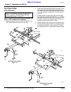
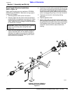
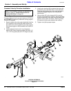
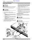
Lift Type Cutter 3-Point Assembly
Figure 1-3
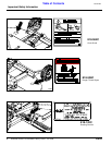
the A-Frame hitch. Securethe A-Frame hitchwith the
3/4" bolts (#15), 3/4" flat washer (#13) and 3/4" lock
nut (#12).
2. Place the 2" long bushing (#17) between the A-
Frame hitch as shown and insert 1” bolt (#9) through
the hole in the hitch and bushing. Secure with the 1”
lock nut (#10).
3. Assemble the two short braces (#8) that are on the
rear brace (#1) between the back holes of the
A-Frame (#11) using the clevis pin (#18) provided
and secure with the flat washer (#21) and cotter pin
(#19).
4. Assemble the two longer straight braces (#5) to the
front hole of the lug that is welded behind the
gearbox mount. Secure with the 1" bolt (#6) and lock
nut (#7).
5. Assemblethe formed rear braces (#2) to theinside of
the inner most lugs at the rear of the cutter. Secure
with the 3/4” bolt (#3) and lock nut (#4).
6. Install the other clevis pin (#18), flat washer (#21)
and cotter pin (#19) into the top front hole of the A-
Frame.
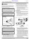
Driveline Installation
1. Attach the slip-clutch end of the driveline (#16) to the
gearbox input shaft securely. Make certain that the
slip-clutch is fully onto the input shaft splines.
Tighten the conical dog pin on back side of slip-
clutch to 45-50 ft-lb torque.
2. Secure chain #20 to hole in driveline guard. Driveline
guard not shown.
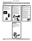
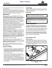
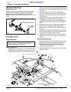
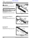
Gearbox Vent Plug
Refer to Figure 1-2
Gearbox vent plugs are shipped loose and packaged
with the Operator’s Manual. Remove existing splitter
gearbox pipe plug and replace with 3/8” vent plug.
Remove wing box pipe plugs and replace with 1/2” vent
plugs.
Figure 1-2
Lift-Type Cutter
Hitch Assembly
Refer to Figure 1-3:
1. Assemble the A-Frame hitch (#11) to the lower bolt
holes of the front inside hitch ears as shown. Insert
the 5/8" long bushings (#14) into the bottom holes of
22320
1/2” Wing Box Pipe Plug
1/2” Wing Box
Pipe Plug
3/8” Splitter Box Pipe Plug
NOTE: Do not tighten hardware until assembly is
complete. Refer to “Torque Values Chart for
Common Bolt Sizes” on page 38.
22289