


10
Section 1: Assembly and Set-Up
RCR2596, RCR2510 and RCRM2510 Rotary Cutters 312-753M
5/09/08
Land Pride
Table of Contents
Section 1: Assembly and Set-Up
Tractor Requirements
Weight & Horsepower
Tractor horsepower and weight must be capable of
controlling the cutter under all operating conditions.
Tractors outside the horsepower range must not be used.
• RCR2596 cutters
Three-point. . . . . . . . 45-110 HP
Pull-type. . . . . . . . . . 30-110 HP
• RCR2510 & RCRM2510 cutters
Three-point. . . . . . . . 50-110 HP
Pull-type. . . . . . . . . . 35-110 HP
PTO Type & Speed
Tractor’srear power take-off (PTO)speed and splinetype
must be capable of matching the cutter’s PTO type and
speed.
• RCR2596 and RCR2510 cutters
540 RPM 1 3/8”-6 spline rear power take-off
• RCRM2510 cutters
1000 RPM 1 3/8”-21 spline rear power take-off
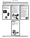
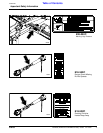
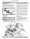
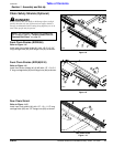
Pull-Type Hitch
Refer to Figure 1-1
Distances between center of drawbar hitch pin hole to
end of tractor PTO shaft (“A” dimension) and from top of
drawbar hitch to center of PTO shaft (“B” dimension)
must be maintained when using the Pull-type hitches.
• “A” = 14" for 540 rpm
• “A” = 16" for 1000 rpm
• “B” = 8” for 540 and 1000 rpm
PTO to Drawbar Distances
Figure 1-1
NOTE: Ballast may need to be added to your tractor
to maintain steering control. Refer to your tractor’s
operator manual to determine if one needs
additional ballast.
IMPORTANT: PTO damage may occur if distances
“A” and “B” are not properly maintained.
22273
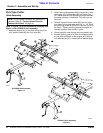
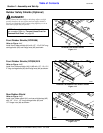
3-Point Hitch
The lower 3-Point arms of the 3-Point hitch must be
stabilized to prevent side-to-side movement. Most
tractors have sway blocks or adjustable chains for this
purpose. Category of hitch is dependent upon the series
of cutter being used.
• RCR2596 (Category l or ll hitch)
• RCR2510 & RCRM2510 (Category ll or lll hitch)
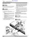
Dealer Preparations
Read and understand the operator’s manual for your
cutter. An understanding of how it works will aid in the
assembly and setup of your cutter.
This Rotary Cutter has been partially assembled at the
factory. However, some assembly will be necessary to
attach the hitch, driveline and guards to the cutter.
It is best to go through the Pre-Assembly Checklist
before assembling the cutter. Speed up your assembly
task and make the job safer by having all the needed
parts and equipment readily at hand.
Pre-Assembly Checklist
Check Reference
Fasteners and pins that were shipped
with the cutter. NOTE: All hardware from
the factory has been installed in the
location where it will be used. If a part or
fastener is temporarily removed for
assembly reasons, remember where it
goes.Keep the parts separated.
Operator’s
Manual
Be sure the parts get used in the correct
location. By double checking while you
assemble, you will lessen the chance of
using a bolt incorrectly that may be
needed later.
Operator’s
Manual
All grease fittings are in place and
lubricated.
Section 5
Page 32
Safety labels are correctly located and
legible. Replace if damaged.
Safety
Information
pg. 1
Inflate tires to specified PSI air pressure.
Tighten wheel bolts to specified torque.
Section 8
Page 38
Red and amber reflectors are correctly
located and visible when the cutter is in
the transport position.
Safety
Information
Page 1
Have a minimum of 2 people at hand
while assembling the cutter.
Operator’s
Manual
Have a fork lift or loader along with
chains and safety stands that are sized
for the job ready for the assembly task.
Operator’s
Manual