


14
Section 1: Assembly and Set-Up
RCR2596, RCR2510 and RCRM2510 Rotary Cutters 312-753M
5/09/08
Land Pride
Table of Contents
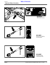
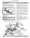
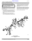
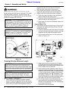
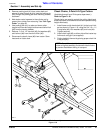
Constant Velocity Driveline Installation
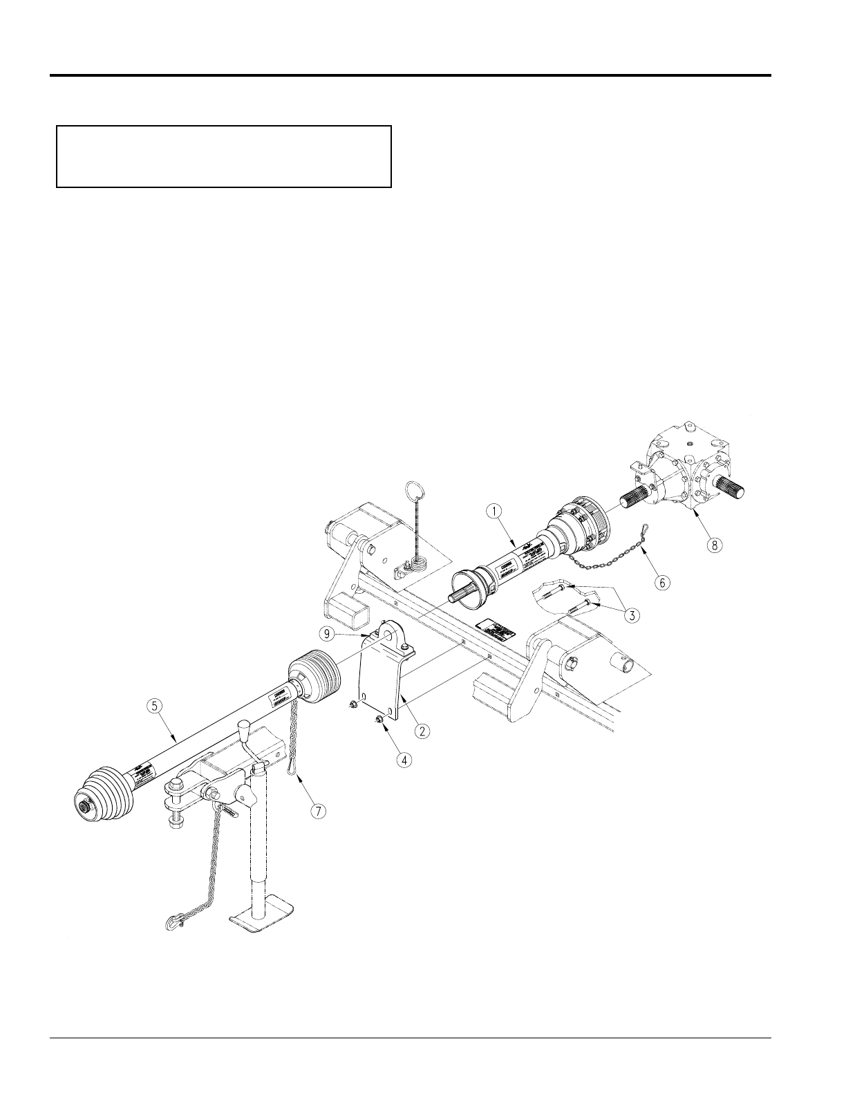
Refer to Figure 1-7:
Constant velocity driveline can be installed on RCR2510
and RCRM2510 cutters only. Maximum turning angle is
limited to 80 degrees.
1. Securely attach slip-clutch end of jackshaft driveline
(#1) to gearbox input shaft (#8). Make certain the
slip-clutch is fully on the gearbox input shaft. Tighten
the conical dog pin on the connection to 45-50 ft-lb
torque.
2. Insert jackshaft driveline (#1) into pillow block
bearing (#9). Secure bearing support (#2) with 1/2”-
13 x 3 1/2” long bolts (#3) and 1/2” flange nuts (#4).
NOTE: Do not tighten hardware until assembly is
complete. Refer to “Torque Values Chart for
Common Bolt Sizes” on page 38.
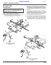
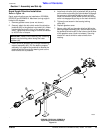
3. Install main driveline (#5) to jackshaft driveline (#1)
by attaching the (red) slide collar on the jackshaft.
Twist the quick disconnect on the yoke and push it
forward to engage the groove on the jackshaft
splined stub.
4. Secure chain (#7) to the tongue (#10) to restrict
driveline outer shield from rotating. Secure jackshaft
driveline chain (#6) to the hole in the left side of the
gearbox cover (cover not shown). Securing chains
will restrict driveline outer shields from rotating.
5. Tighten nuts (#4) to proper torque.
RCR2510 & RCRM2510
Constant Velocity Driveline Assembly
Figure 1-7
22304