


23
Section 2: Adjustments
5/09/08
RCR2596, RCR2510 and RCRM2510 Rotary Cutters 312-753M
Land Pride
Table of Contents
Cutting Height Adjustment
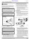
!
DANGER!
Engage parking brake, disengage PTO, shut off tractor and
remove key before proceeding. Ensure that all moving parts
have come to a complete stop before dismounting from the
tractor.
!
CAUTION!
Wear a pair of gloves when performingthis operation. Goto the
back of the cutter and carefully rotateeach blade to the position
shown in Figure 2-3. Avoid direct contact with the cutting edge
of the blade.
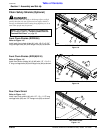
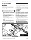
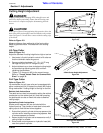
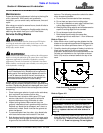
Refer to Figure 2-3:
Measure distance from cutting tip of the front cutting
blade to ground surface. This distance is the cutting
height.
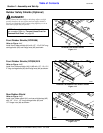
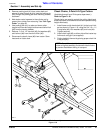
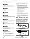
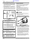
Lift-Type Cutter
Refer to Figure 2-4:
Adjust the tailwheel if cutting height is too high or too low.
1. Use tractor’s 3-point hydraulic control to lift cutter so
that the tailwheel clears the ground.
2. Remove existing hardware; 1/2” -13 x 1 1/2" long
carriage bolt (#1) and 1/2” flange nut (#2).
3. Adjust tailwheel up or down to desired cutting height
by repositioning adjusting plate (#3) and then
replacing the hardware.
4. Tighten 1/2” flange nut (#2) to the correct torque.
Refer to “Torque Values Chart for Common Bolt
Sizes” on page 38.
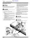
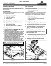
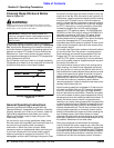
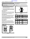
Pull-Type Cutter
Refer to Figure 2-5:
Lift mechanism for pull-type units can be equipped with
either a ratchet jack (#1)or hydraulic cylinder (#2). Adjust
lifting mechanism if cutting height is too high or too low.
Ratchet Jack Instructions
The deck can be raised or lowered by setting the ratchet
mechanism on the ratchet jack (#1) and then pumping
the jack handle to raise or lower the cutter to desired
cutting height.
Hydraulic cylinder Instructions
Stroke control spacers (#3) are included with the
hydraulic set-up. They consist of cast steel halves with
spring clips to hold the two halves together.
1. Extend the hydraulic cylinder to free up space on the
cylinder rod for installing and removing spacers. Add
or remove spacers as needed.
2. Retract hydraulic cylinder and re-measure to verify if
cutting height is suitable.
3. Store stroke control spacers on hydraulic hose (#4)
near the hydraulic cylinder.
Cutting Height
Figure 2-3
3-Point Cutter Height Adjustment
Figure 2-4
Pull-Type Lift Selections
Figure 2-5
22316
16269
22318