


20
Section 1: Assembly and Set-Up
RCR2596, RCR2510 and RCRM2510 Rotary Cutters 312-753M
5/09/08
Land Pride
Table of Contents
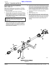
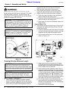
7. Attach driveline yoke end (#8) to tractor PTO shaft.
Secure with locking device. Pull on both end of the
driveline to make sure it is secured to the tractor and
gearbox shafts.
8. Attach hydraulic hose (#9) to tractor hydraulic outlet.
9. Fully retract the jack stand (#1), remove locking pin
(#2) and store parking jack on the cutter deck with
locking pin as shown.
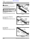
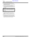
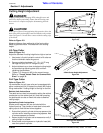
Safety Chains
Refer to Figure 1-17:
When towing implements on the highway, use a safety
chain (#7) with tensile strength equal to or greater than
the gross weight of the implement to be towed by the
tractor. This will control the implement in the event the
hitch pin is lost.
Attaching safety chain (#7) to the tractor. Lock chain
hook securely to the safety chain. Make a trial run by
driving the tractor to the right and to the left for a short
distance to check the safety chain adjustment. If
necessary, re-adjust to eliminate a tight or loose chain.
Pull-Type Tractor Un-Hook
Refer to Figure 1-17
1. Park cutter ona levelsolid hard surface.Place tractor
gear selector in park and set park brake.
NOTE: May need to adjust the leveling rod nut
couplers to obtain correct drawbar height.
NOTE: Always place jack stand on firm surface or
place board under jack stand for support.
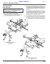
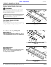
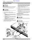
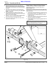
Pull-Type Tractor Hook-Up
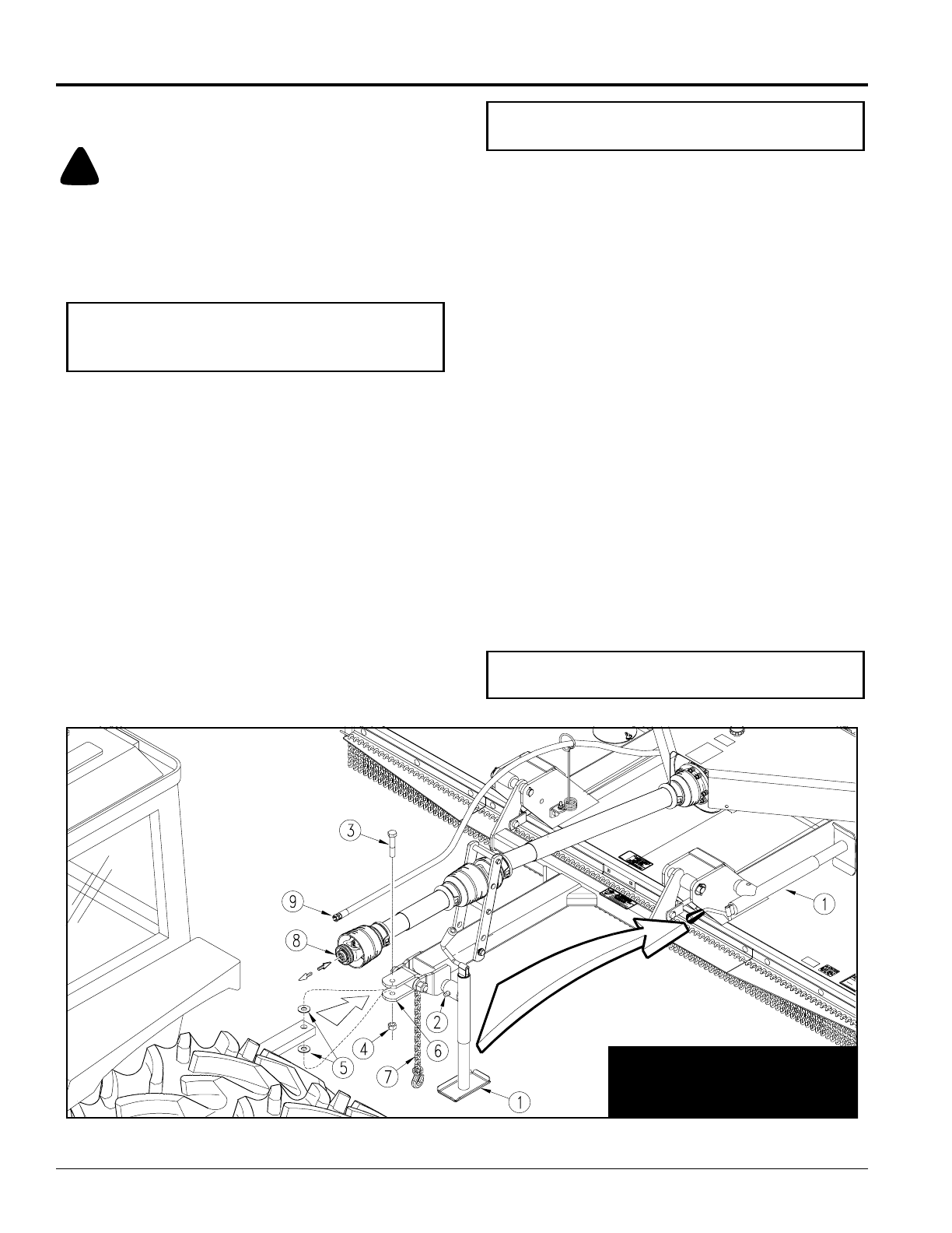
Figure 1-17
RCR2510 is shown. Jack is located
onthe deckin thetransportposition
on the RCR2596.
Pull-Type Tractor Hook-Up
Refer to Figure 1-17
!
DANGER!
Crushing Hazard between tractor and implement. Do not allow
anyone to stand between the tractor and implement while
backing-up to an implement. Never operate the hydraulic
3-point lift controls while someone is directly behindthe tractor.
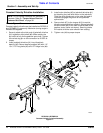
Refer to Figure 1-17:
1. Make certain jack stand (#1) is properly attached to
the cutter hitch and secured with attachment pin
(#2).
2. Back tractor within close proximity of cutter
clevis (#6).
3. Raise or lower jack (#1) to align clevis (#6) with
tractor drawbar. Drawbar should fit between lower
and upper plates of clevis.
4. Back tractor up to cutter hitch until holes in the
drawbar and clevis (#6) are aligned.
5. Insert 1" flat washers (#5) above and below tractor
drawbar.
6. Insert 1” -8 x 4 1/2” gr5 hex bolt (3) through top of
clevis (#6), 1" washer (#5), drawbar, remaining 1"
washers (#5) and out through bottom of clevis (#6).
Secure hex bolt with locknut (#4). Tighten nut snugly
to remove all play and then back nut one-quarter
turn.
IMPORTANT: Jack attachment pin (#2) must be fully
inserted and secured before working on or around a
cutter that is not hooked to the tractor drawbar.