


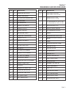
Section 7
DISASSEMBLY AND EXPLODED VIEWS
Page 67
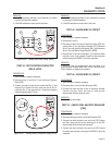
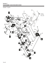
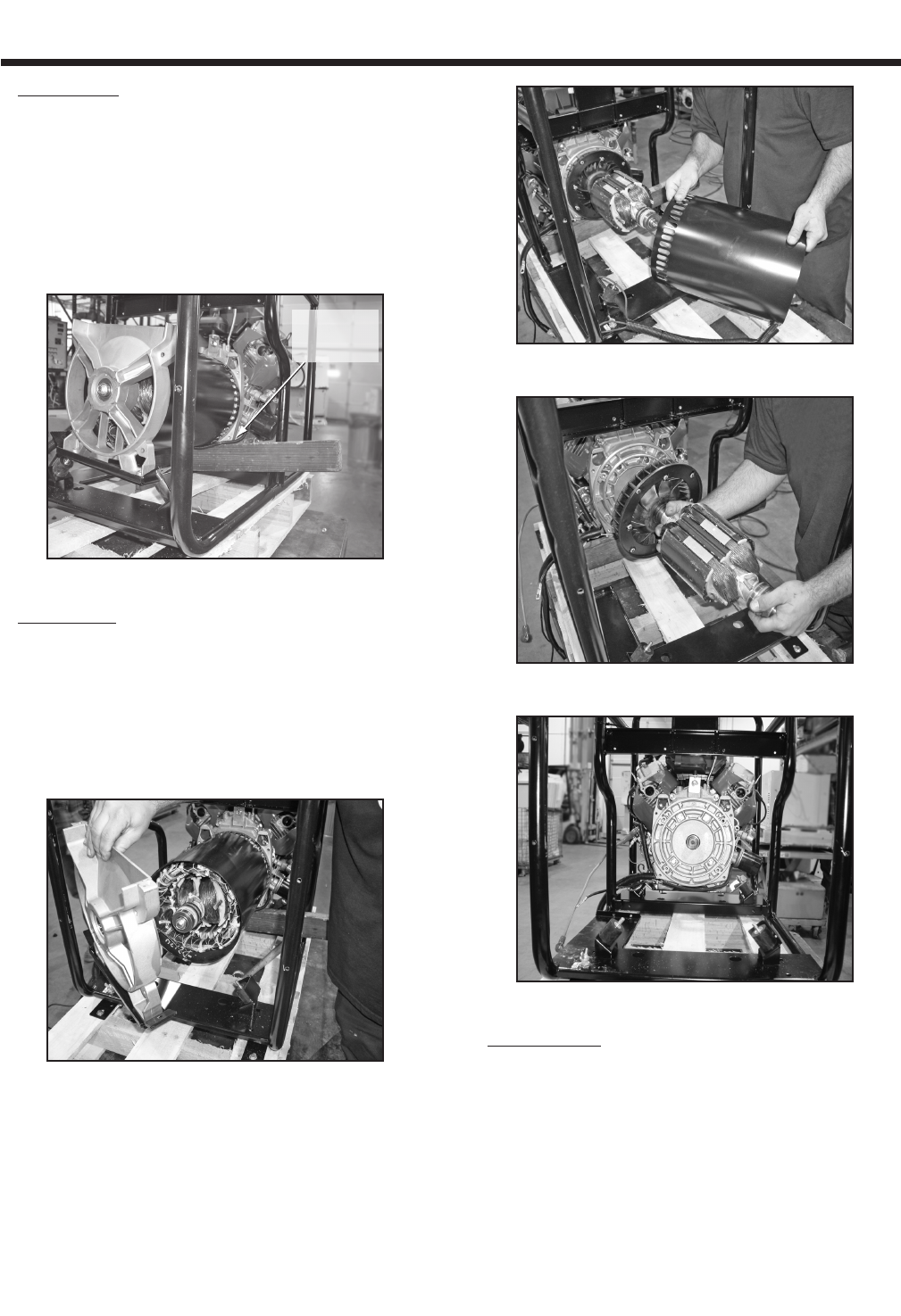
6. Remove Stator. Disconnect Wire 4 and Wire 0 from the brush
assembly, Figure A, Item 21. Remove the brush assembly.
Remove the four stator hold down bolts, Figure A, Item 12. Lift
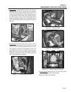
the rear end of the alternator up to clear the muffler frame from
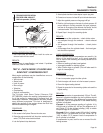
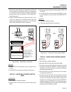
the rubber alternator mount, place a 2x4 under the front bear-
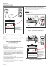
ing carrier for support. Using a rubber mallet carefully remove
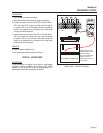
the rear bearing carrier, Figure A, Item 4. Rotate the rotor so
that the steel laminations face the top and bottom. Remove the
stator can.
2 x 4 UNDER
BEARING
CARRIER
Figure 7-6. – Support Alternator
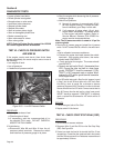
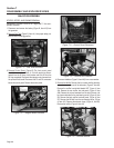
7. Remove Rotor. Remove rotor bolt, Figure A, Item 11. Cut 2.5
inches from the hex head end of the rotor bolt. Slot the end
of the bolt to suit a flat blade screwdriver. Slide the rotor bolt
back through the rotor and use a screwdriver to screw it into
the crankshaft. Use a 3” M12 x 1.75 bolt to screw into the rotor.
Apply torque to the 3” bolt until the taper breaks. If necessary,
when torque is applied to the 3” bolt, use a rubber mallet on the
end of the rotor shaft to break the taper.
Figure 7-7. – Remove Bearing Carrier
Figure 7-8. – Remove Stator
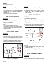
Figure 7-9. – Remove Rotor
Figure 7-10. – Engine Ready for Removal
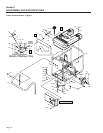
8. Remove Engine. Remove the four nuts from rubber engine
mounts (Figure A, Item #29). Remove engine.
Reverse procedure for assembly.